-
01 - 35
-
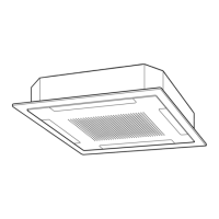
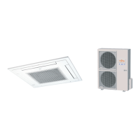
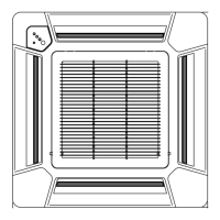
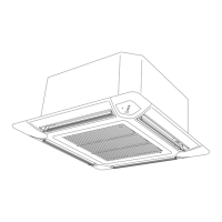
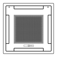
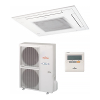
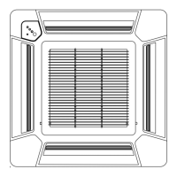
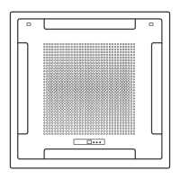
CASSETTE TYPE
AU
G12-24LVL
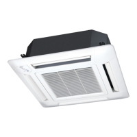
CASSETTE TYPE
AU
G12-24LVL
EXTERNAL INPUT & OUTPUT11.
Connector INPUT OUTPUT REMARKS
CN102 Control input —
See external
input/output settings for
details.
CN103 — Operation status output
CN6 — Fresh air control output
EXTERNAL INPUT11-1.
CONTROL INPUT (Operation/Stop or Forced stop)
The air conditioner can be remotely operated by means of the following on-site work.
"Operation/Stop" mode or "Forced stop" mode can be selected with function setting of indoor unit.
Unit operation is started at the following contents by adding the contact input of a commercial ON/OFF switch to a
connector on the external control PC board and turning it ON.
Unit operation Initial setting after turned power ON Starting mode other than initial setting
Operation mode Auto changeover Mode at previous operation
Set temperature 24°C Temperature at previous operation
Air flow mode AUTO Mode at previous operation
Up-down air direction (swing) Standard air direction (swing OFF) Air direction at previous operation
Left-right air direction (swing) Standard air direction (swing OFF) Air direction at previous operation
Circuit diagram example
Indoor
control PC board Connected unit
Ex.) Switch
Connector
1
3
Signal
Field supply
* Make the distance from the PC board to the connected unit within 10m.
*10 m
Contact capacity : 24VDC or more, 10mA or more.
Please use non-polar relays and switches.
When function setting is in "Operation/Stop" mode ●
Operation
Stop
ON
OFF
Input signal
Indoor unit
When function setting is in "Forced stop" mode ●
Parts (Optional)
Model name
UTY-XWZX
Wire (External input)
Remote controller
ON ON ON
nput signal
ON
OFF
Indoor unit
Operation
Stop
Command
Forced stop
Normal
Remote control
operation invalidity
 Loading...