En-8
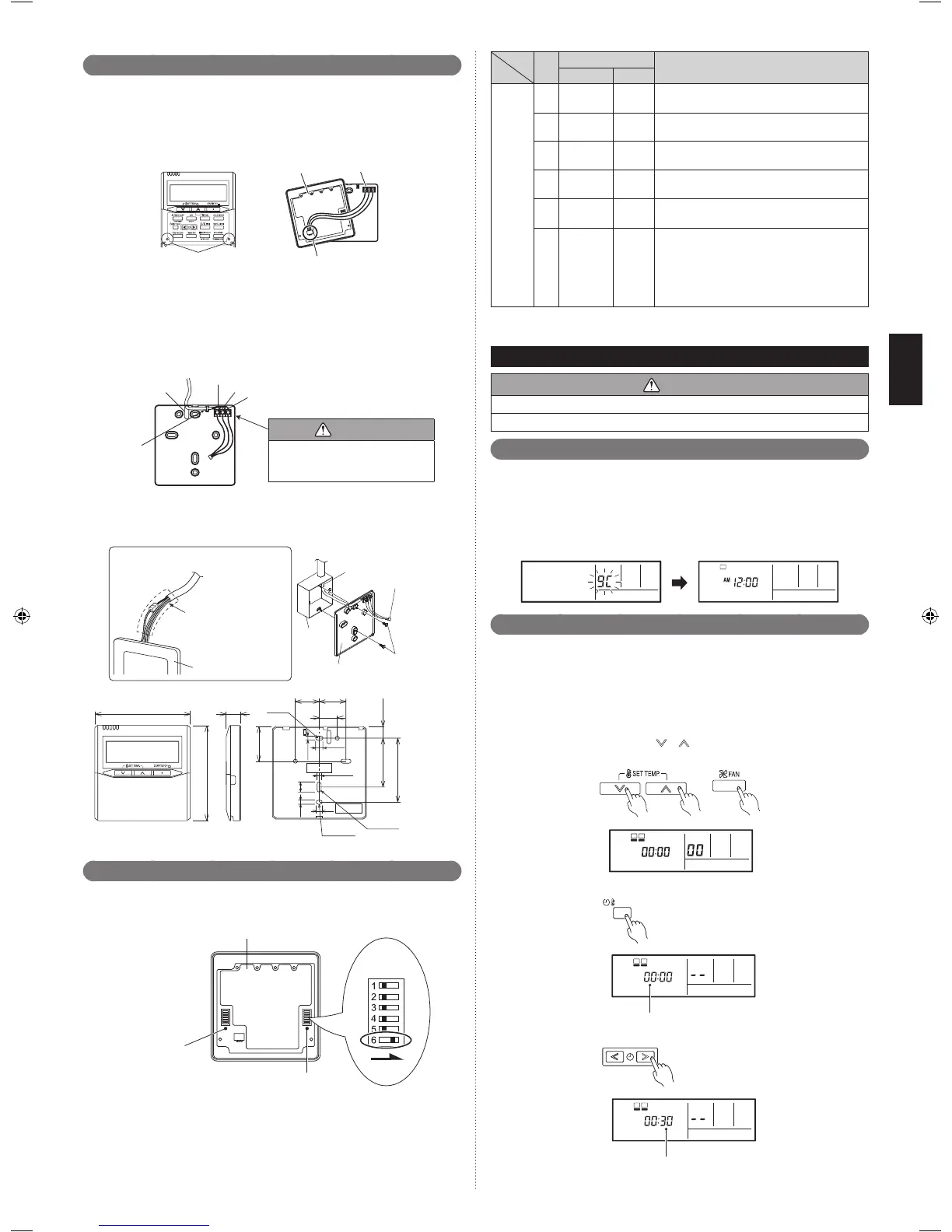
Installing the remote controller7. 1.
Open the operation panel on the front of the remote controller, remove the 2 screws
indicated in the following gure, and then remove the front case of the remote controller.
When installing the remote controller, remove the connector from the front case. The wires
may break if the connector is not removed and the front case hangs down.
When installing the front case, connect the connector to the front case.
Screws
Connector
Front case
(back side)
Rear case
When remote controller cable is embedded•
Embed the remote controller cable and box.(1)
Pass the remote controller cable through the hole in the rear case and connect the (2)
remote controller cable to the remote controller terminal blocks specied in gure.
Clamp the remote controller cable sheath with the cable tie as shown in gure.(3)
Cut off the excess cable tie.(4)
Install the rear case to the wall, box, etc., with 2 screws gure.(5)
1. R (Red)
2. W (White)
3. B (Black)
Hole
Cable tie
(Small)
CAUTION
When connecting the remote
controller wires, do not overtighten
the screws.
Seal the cable outlet with putty to prevent dew condensation or insect from entering the box.
[Example] •
Remote
controller cable
Connector
Screws
Rear case
Box
Ground the remote controller if it has
a earth (ground) wire.
Remote controller
Wrap the connector
and remote controller
wires with vinyl tape
or some other type of
insulation as shown
Hole
Hole 2
Hole 3
Unit : mm
33.5
4.5
4.5
4.5 12.5
45.3
63.5
83.5
15.3
30
23
8
6
Setting the dip switches7. 2.
Set the remote controller DIP switches.
[Example]
Front case (back side)
DIP switch 1
Do not use this
DIP switch 2
OFF ON
ON
No.
SW state
Detail
OFF ON
DIP
switch
1
1
♦
Cannot be used.
(Do not change)
2
♦
Dual remote controller setting
*Refer to 11.3. Dual remote controllers
3
♦
Cannot be used.
(Do not change)
4
♦
Cannot be used.
(Do not change)
5
♦
Cannot be used.
(Do not change)
6
♦
Invalidity Validity
Memory backup setting
* Set to ON to use batteries for the memory
backup.
If batteries are not used, all of the settings
stored in memory will be deleted if there is a
power failure.
(
♦
: Factory setting)
FUNCTION SETTING8.
CAUTION
Conrm whether the wiring work for outdoor unit has been nished.
Conrm whether the cover for electric control box on the outdoor unit is close.
Turning on the power8. 1.
Check the remote controller wiring and DIP switch settings.(1)
Install the front case. When installing the front case, connect the connector to the front (2)
case.
Check the indoor and outdoor unit wiring and circuit board switch settings, and then (3)
turn on the indoor and outdoor units. After “9C” has ashed on the set temperature
display for several seconds, the clock display will appear in the center of the remote
controller display.
The clock display will appear in the center of the remote controller display.
Setting method8. 2.
This procedure changes to the function settings used to control the indoor unit according •
to the installation conditions.
Incorrect settings can cause the indoor unit malfunction.•
After the power is turned on, perform the “FUNCTION SETTING” according to the •
installation conditions using the remote controller.
The settings may be selected between the following two:•
Function Number or Setting Value.•
Settings will not be changed if invalid numbers or setting values are selected.•
Press the set temperature buttons ((1)
) ( ) and fan control button simultaneously for
more than 5 seconds to enter the function setting mode.
Press the SET BACK button to select the indoor R.C. address.
R.C. address of INDOOR UNIT
Press the set time buttons to select the function number.(2)
9380441038_IM.indb 8 28/1/2556 13:44:41