En-12
Option parts
External input/output wire
Insulated connection
Field supply
• Connection terminals
CN100
Operation status
output (White)
CN103
Control input
(Operation/stop)
(White)
CN101
Error status
output (Black)
CN160
External electrical
heater control
output (Orange)
CN161
Fresh air control
output (Green)
CLIP
Cable tie (Medium)
I.R. receiver unit / Remote sensor12. 2.
Connection method
• Connection terminals
I.R. receiver unit
(CN130)
Remote sensor (CN113)
• Wiring arrangement
CLIP
Cable tie (Medium)
Connector
I.R. receiver unit
• Use 7 pins for I.R. receiver unit cable
Remote sensor
Remove the existing connector and replace it with the remote sensor connector (ensure •
that the correct connector is used).
The original connector should be insulated to ensure that i• t does not come into contact
with other electrical circuitry.
Setting for room temperature control setting
When a remote sensor is connected, set the function setting of indoor unit as indicated
below.
Set Function Number “48” (Room temperature setting) to “01”•
Setting for room temperature correction
When a remote sensor is connected, set the function setting of indoor unit as indicated
below.
Set Function Number “30” (Cooler air temperature correction) to “01”•
Set Function Number “31” (Heater air temperature correction) to “01”•
CUSTOMER GUIDANCE13.
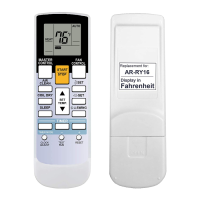
Explain the following to the customer in accordance with the operating manual:
Starting and stopping method, operation switching, temperature adjustment, timer, air (1)
ow switching, and other remote controller operations.
Air lter removal and cleaning, and how to use the air louvers.(2)
Give the operating and Installation Manuals to the customer.(3)
If the signal code is changed, explain to the customer how it changed (the system (4)
returns to signal code A when the batteries in the remote controller are replaced).
*(4) is applicable to using wireless remote control.