En-10
Setting the room temperature detection location8. 4.
The detection location of the room temperature can be selected from the following two •
examples. Choose the detection location that is best for the installation location.
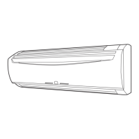
A. Indoor unit setting (factory setting)
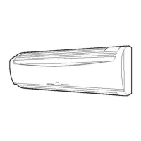
The room temperature is detected by the indoor unit temperature sensor.•
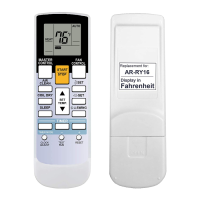
When the THERMO SENSOR button is pressed, the lock display ashes because the (1)
function is locked at the factory.
Indoor unit
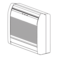
B. Indoor unit/remote controller setting (room temperature sensor selection)
The temperature sensor of the indoor unit or the remote controller can be used to detect
the room temperature.
Enable the room temperature sensor selection in FUNCTION SETTING, which will be (1)
described later.
Press the THERMO SENSOR button for 5 seconds or more to select the temperature (2)
sensor of the indoor unit or the remote controller.
Indoor unit
NOTE
If the function to change the temperature sensor is used as shown in examples A (other
than example B), be sure to lock the detection location.
If the function is locked, the lock display
will ash when the THERMO SENSOR
button is pressed.
CAUTION
If the difference between the room temperature and wall temperature is great as the
external and internal walls are joined and the wall temperature is easily affected by the
outside air, the detected temperature may be different from the actual room temperature
because the sensor of the remote controller detects the temperature near the wall surface.
Especially when the remote controller is installed on a wall that is directly exposed to the
outside air, it is recommended to use the indoor unit temperature sensor.
Do not use the temperature sensor of the remote controller as a substitute for the
indoor unit temperature sensor which has problem in the temperature detection. (Solve
the problem of the indoor unit temperature sensor.)
If the unit is installed in a room with a ceiling of 3 m or higher, the temperature may not
be detected properly with the indoor unit temperature sensor as there may be a large
difference between the temperature near the ceiling and the oor.
In this case, it is recommended to take a measure such as installation of an optional
remote sensor and room air ventilation using a circulator.
TEST RUN9.
CHECK ITEMS
Is operation of each button on the remote control unit normal?(1)
Is the drain normal?(2)
Is there any abnormal noise and vibration during operation?(3)
Do not operate the air conditioner in the running state for a long time.(4)
[Operation method]
For the operation method, refer to the Operating Manual.•
Stop the air conditioner operation.(1)
Press the MODE button and the FAN button simultaneously for 2 seconds or more to (2)
start the test run.
Test run display
Press the START/STOP button to stop the test run.(3)
If “C0” appears in the R.C. address display, there is a remote controller error.
R.C. address Error code Content
C0 15 Incompatible indoor unit is connected
C0 12
Indoor unit ↔ remote controller
communication error
CHECK LIST10.
Pay special attention to the check items below when installing the indoor unit(s). After
installation is complete, be sure to check the following check items again.
Check items If not performed correctly
Check
box
Has the indoor unit been installed
correctly?
Vibration, noise,
indoor unit may drop
Has there been a check for gas leaks
(refrigerant pipes)?
No cooling, No heating
Has heat insulation work been
completed?
Water leakage
Does water drain easily from the
indoor units?
Water leakage
Is the voltage of the power source the
same as that indicated on the label on
the indoor unit?
No operation, heat or burn damage
Are the wires and pipes all connected
completely?
No operation, heat or burn damage
Is the indoor unit grounded? Short circuit
Is the connection cable the specied
thickness?
No operation, heat or burn damage
Are the inlets and outlets free of any
obstacles?
No cooling, No heating
After installation is completed, has the
proper operation and handling been
explained to the user?
Operate the unit according to the
operating manual provided, and check
that it is operating normally.
SPECIAL INSTALLATION METHODS11.
CAUTION
Be sure to turn off the electrical breaker before making settings.
When setting DIP switches, do not touch any other parts on the circuit board directly
with your bare hands.
Group control system11. 1.
A number of indoor units can be operated at the same time using a single remote controller.
(1) Wiring method (indoor unit to remote controller)
1 2 3 1 2 3 1 2 3 1 2 3
1 2 3
Indoor unit 0 Indoor unit 1 Indoor unit 2 Indoor unit 3
Bus wire
Remote
controller cable
Remote controller
R W B
When earth (ground) wire is necessary
(2) Set the R.C. address (DIP switch setting)
Set the R.C. address of each indoor unit using the DIP switch on the indoor unit
circuit board.
The DIP switch is normally set to 0.
9380441038_IM.indb 10 28/1/2556 13:44:43