En-12
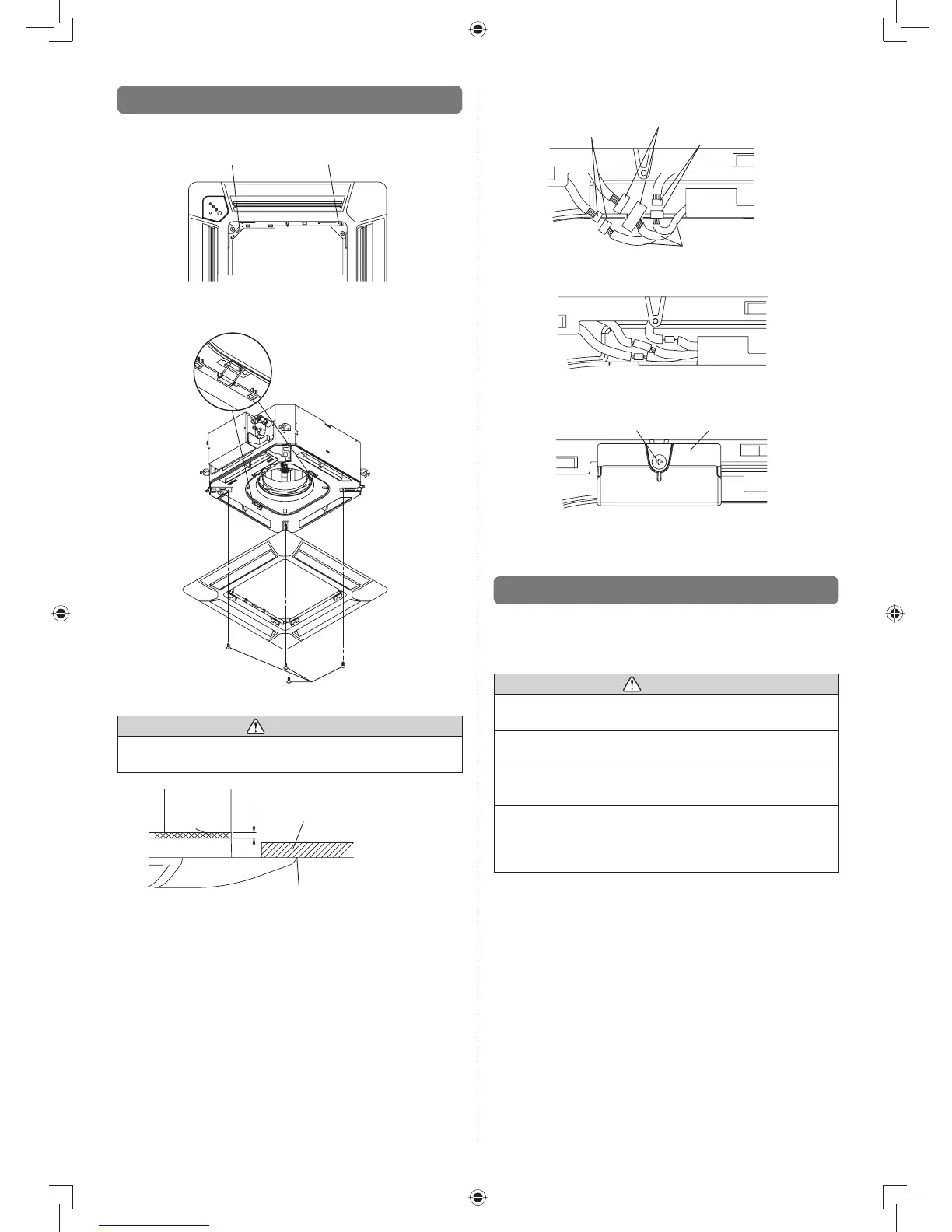
Connect the connector.(2)
Wire (louver): WHITE
Wire (display): WHITE
Wire (louver): RED
Indoor unit side
Arrange the wires as illustrated below.•
Attach the connector cover.(3)
Screw Connector cove
8.3. Attach the intake grille
The installation is the reverse of “REMOVING THE INTAKE
GRILLE”.
The intake grille can be rotated and installed 4 ways to suit
the user’s preference.
CAUTION
The louver angle cannot be changed if the power is not •
on. (If moved by hand, it may be damaged.)
The grille assembly is directionally relative to the air •
conditioner body.
Install so that there is no gap between the grille assem-•
bly and the air conditioner body.
The decoration panel equips with an accessory to •
prevent the grill completely open. Be sure to read the
INSTALLATION SHEET included with the decoration
panel before installation.
8.2. Installing the panel to indoor unit
Install the decoration panel on the indoor unit.(1)
“DRAIN” mark “PIPE” mark
Align the stamped marks on the decoration panel against •
the pipe and the drain of the indoor unit.
Screw
CAUTION
Use only the supplied screws to install the decoration •
panel.
Indoor unit
Ceiling
No gap between ceiling and
decoration panel around entire
periphery
5 ~ 7
Decoration panel
Sealant