En-18
10. TEST RUN
CHECK ITEMS
Is operation of each button on the remote control unit (1)
normal?
Does each lamp light normally?(2)
Do not air fl ow direction louvers operate normally?(3)
Is the drain normal?(4)
Is there any abnormal noise and vibration during opera-(5)
tion?
Do not operate the air conditioner in the running state for a •
long time.
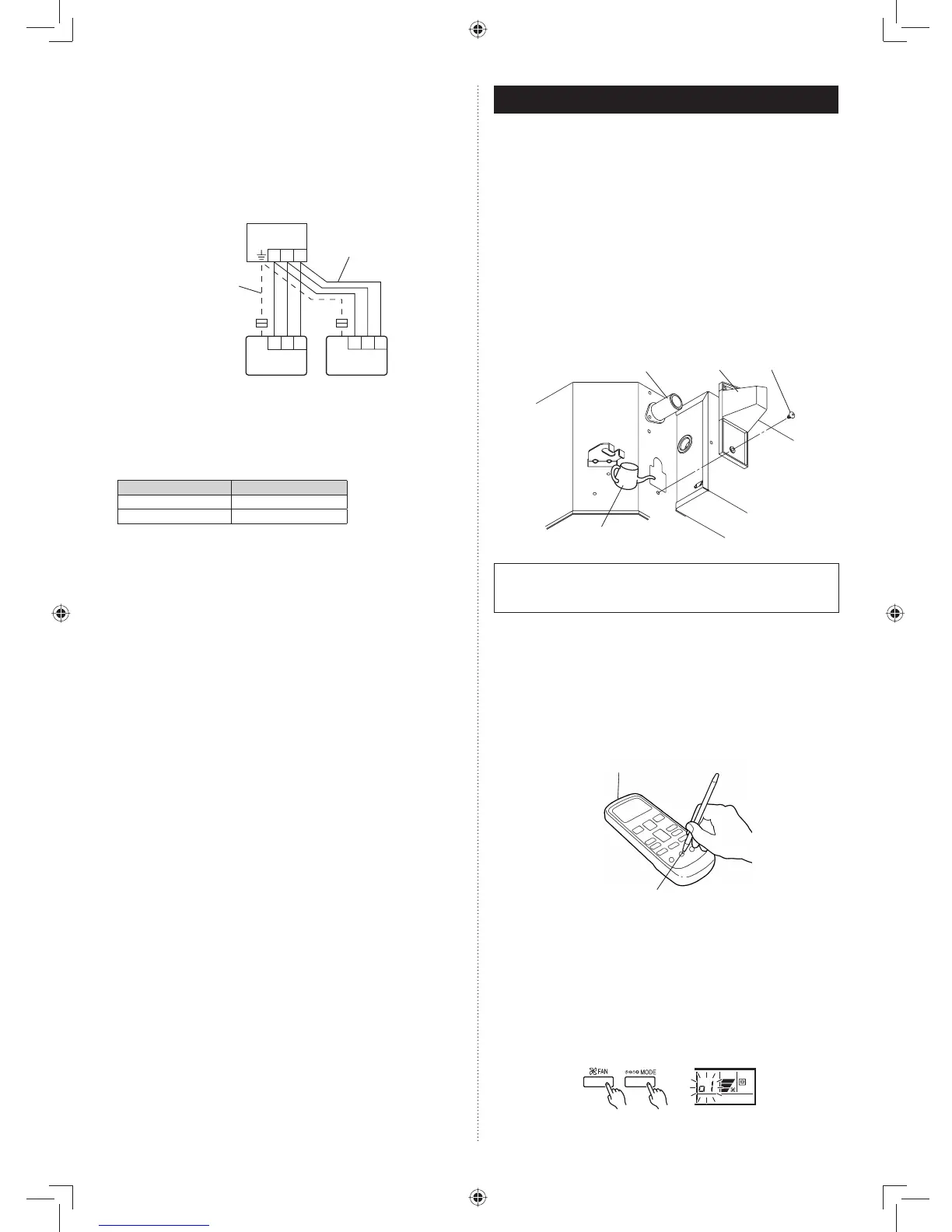
CHECKING DRAINAGE.
To check the drain, remove the water cover and fi ll with 1 liter
of water as shown in the fi gure.
The drain pump operates when operating in the cooling
mode.
Wire cover
Drain pipe
Watering pot
Screw
• Test running
When the air conditioner is run by pressing the remote con-
trol unit test run button, the OPERATION and TIMER lamps
fl ash slowly at the same time.
[Operation method]
For the operation method, refer to the operating manual.•
The outdoor unit may not operate depending on the room •
temperature.
In this case, press the test run button on the remote control
unit while the air conditioner is running. (Point the transmit-
ter section of the remote control unit toward the air condi-
tioner and press the test run button with the tip of a ball-
point pen, etc.)
Transmitter section
Test run button
To end test operation, press the remote control unit START/•
STOP button.
(When the air conditioner is run by pressing the test run but-
ton, the OPERATION Lamp and TIMER Lamp will simulta-
neously fl ash slowly.)
[Using the wired remote control] (Option)
For the operation method, refer to the operating manual.•
Stop the air conditioner operation.(1)
Press the master control button and the fan control button (2)
simultaneously for 2 seconds or more to start the test run.
Test run display
Press the start/stop button to stop the test run.(3)
9.4.3. Dual remote controllers
Two separate remote controllers can be used to operate the •
indoor units.
The timer and self-diagnosis functions cannot be used on the •
slave unit of remote controller.
Wiring method (indoor unit to remote controller)(1)
1 231 23
1 2 3
Remote controller cable
Indoor unit
When ground wire
is necessary
Master unit Slave unit
Remote
controller
Remote
controller
Remote controller DIP switch 1 setting (2)
Set the remote controller DIP switch 1-No. 2 according to
the following table.
DIP SW 1-No. 2
Master unit OFF
Slave unit ON