En-6
Pipe outside
diameter [mm (in.)]
Width across fl ats
of Flare nut [mm]
6.35 (1/4) 17
9.52 (3/8) 22
12.70 (1/2) 26
15.88 (5/8) 29
19.05 (3/4) 36
4.3.2 Bending pipes
If pipes are shaped by hand, be careful not to collapse them.•
Do not bend the pipes at an angle more than 90°.•
When pipes are repeatedly bend or stretched, the material •
will harden, making it diffi cult to bend or stretch them any
more.
Do not bend or stretch the pipes more than three times.•
CAUTION
To prevent breaking of the pipe, avoid sharp bends. •
If the pipe is bent repeatedly at the same place, it will •
break.
4.3.3. Pipe connection
CAUTION
Be sure to apply the pipe against the port on the indoor •
unit and the outdoor unit correctly. If the centering is im-
proper, the fl are nut cannot be tightened smoothly. If the
fl are nut is forced to turn, the threads will be damaged.
Do not remove the fl are nut from the indoor unit pipe until •
immediately before connecting the connection pipe.
Do not use mineral oil on fl ared part. Prevent mineral •
oil from getting into the system as this would reduce the
lifetime of the units.
Detach the caps and plugs from the pipes.(1)
Center the pipe against the port on the indoor unit, and (2)
then turn the fl are nut by hand.
Indoor unit
Connection pipe
(Liquid)
Connection pipe
(Gas)
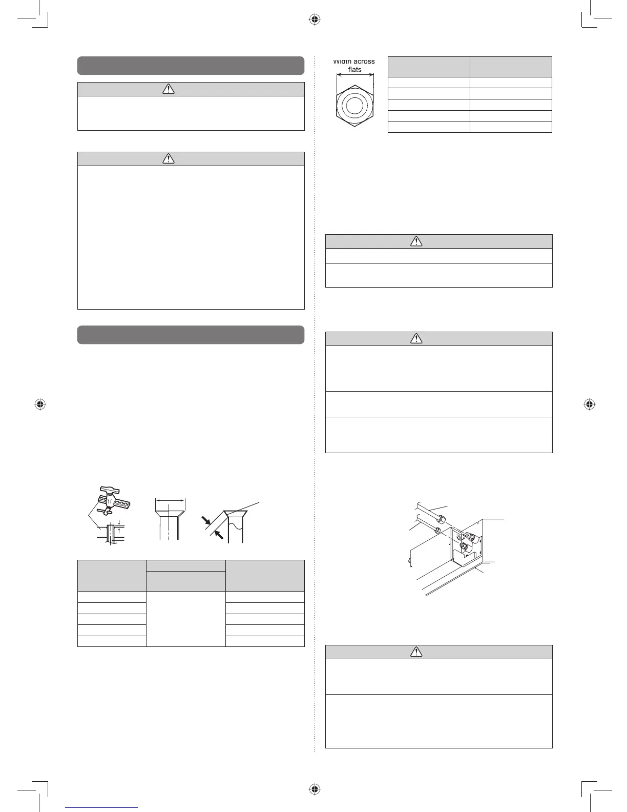
When the fl are nut is tightened properly by your hand, (3)
hold the body side coupling with a separate spanner, then
tighten with a torque wrench. (See the table below for the
fl are nut tightening torques.
CAUTION
Hold the torque wrench at its grip, keeping it in the right •
angle with the pipe, in order to tighten the fl are nut cor-
rectly.
Tighten the fl are nuts with a torque wrench using the •
specifi ed tightening method. Otherwise, the fl are nuts
could break after a prolonged period, causing refrigerant
to leak and generate a hazardous gas if the refrigerant
comes into contact with a fl ame.
4.2. Pipe requirement
CAUTION
Refer to the Installation Manual of the outdoor unit for •
description of the length and the diameter of connecting
pipe or for difference of its elevation.
Use pipe with water-resistant heat insulation.•
CAUTION
Install heat insulation around both the gas and liquid •
pipes. Failure to do so may cause water leaks.
Use heat insulation with heat resistance above 120 °C.
(Reverse cycle model only)
In addition, if the humidity level at the installation loca-
tion of the refrigerant piping is expected to exceed 70%,
install heat insulation around the refrigerant piping. If the
expected humidity level is 70-80%, use heat insulation
that is 15 mm or thicker and if the expected humidity ex-
ceeds 80%, use heat insulation that is 20 mm or thicker.
If heat insulation is used that is not as thick as specifi ed,
condensation may form on the surface of the insulation.
In addition, use heat insulation with heat conductivity of
0.045W/(m·K) or less (at 20 °C).
4.3. Flare connection (pipe connection)
4.3.1. Flaring
Use special pipe cutter and fl are tool exclusive for R410A.•
Cut the connection pipe to the necessary length with a (1)
pipe cutter.
Hold the pipe downward so that cuttings will not enter the (2)
pipe and remove any burrs.
Insert the fl are nut (always use the fl are nut attached to (3)
the indoor and outdoor units respectively) onto the pipe
and perform the fl are processing with a fl are tool. Leak-
age of refrigerant may result if other fl are nuts are used.
Protect the pipes by pinching them or with tape to prevent (4)
dust, dirt, or water from entering the pipes.
B
Die
A
Pipe
Check if [L] is flared uniformly
and is not cracked or scratched.
L
Pipe outside
diameter
[mm (in.)]
Dimension A [mm]
Dimension B
-
0
0.4
[mm]
Flare tool for R410A,
clutch type
6.35 (1/4)
0 to 0.5
9.1
9.52 (3/8) 13.2
12.70 (1/2) 16.6
15.88 (5/8) 19.7
19.05 (3/4) 24.0
When using conventional fl are tools to fl are R410A pipes,
the dimension A should be approximately 0.5 mm more than
indicated in the table (for fl aring with R410A fl are tools) to
achieve the specifi ed fl aring. Use a thickness gauge to meas-
ure the dimension A.