En-9
6.2. Wiring method
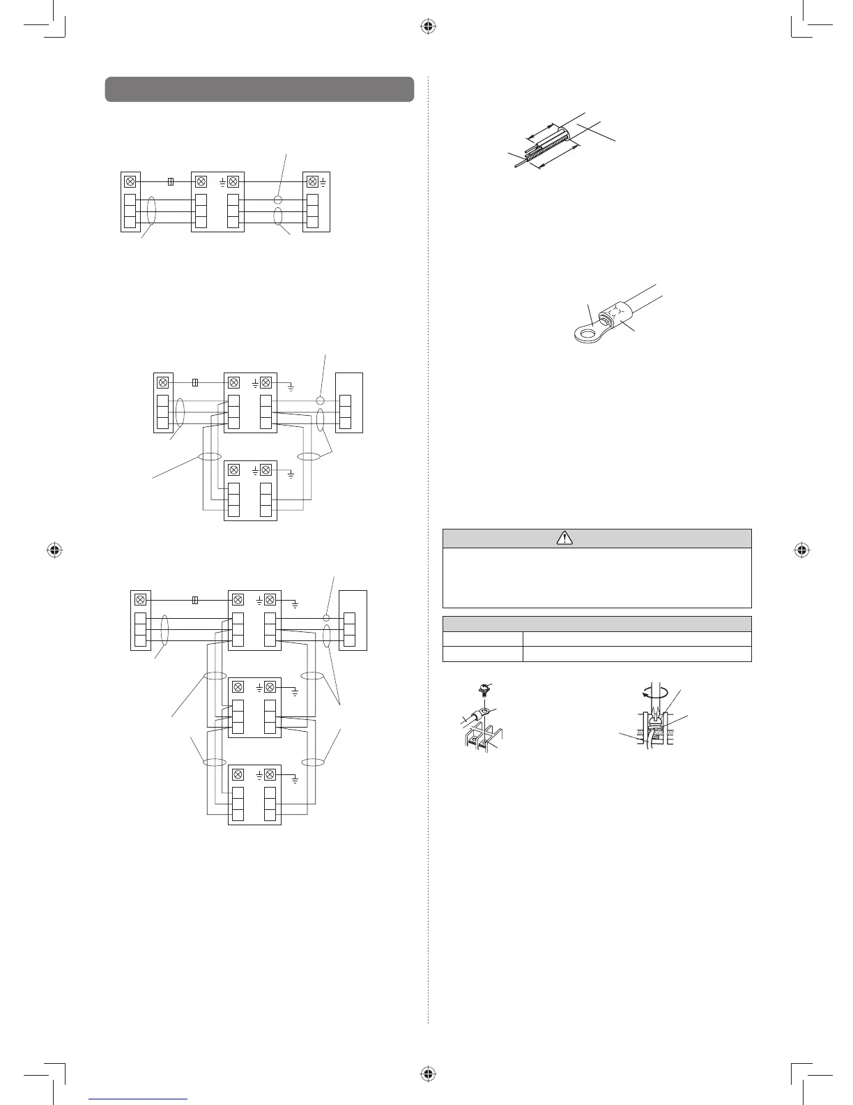
6.2.1. Connection diagrams
(Standard pair)
Indoor unit
B
W
R
3
2
1
3
2
1
3
2
1
Outdoor unit
Wired remote
controller
Black
White
Red
*
Power supply cable
Transmission cable
Remote controller cable
*Ground the remote controller if it has a ground wire.•
Wired remote controller is recommended using simultaneous
twin or triple connection.
(Simultaneous twin)
Indoor unit
(Master)
Indoor unit
(Slave)
B
W
R
3
2
1
3
2
1
3
2
1
Outdoor unit
Wired remote
controller
3
2
1
3
2
1
Black
White
Red
*
Power supply
cable
Bus wire
(Local purchase)
Transmission cable
Remote controller
cable
(Simultaneous triple)
Indoor unit
(Master)
Indoor unit
(Slave)
B
W
R
3
2
1
3
2
1
3
2
1
Outdoor unit
Wired remote
controller
3
2
1
3
2
1
Indoor unit
(Slave)
3
2
1
3
2
1
Black
White
Red
*
Power supply
cable
Bus wire
(Local purchase)
Transmission
cable
Remote controller
cable
Connect the remote controller wires to the master unit.•
*Ground the remote controller if it has a ground wire.•
6.2.2. Connection cable preparation
Keep the earth wire longer than the other wires.•
Power suppl
How to connect wiring to the terminals.
(For strand wiring)
Use crimp-type terminals with insulating sleeves as shown (1)
in the fi gure below to connect to the terminal block.
Securely crimp the crimp-type terminals to the wires using (2)
an appropriate tool so that the wires do not come loose.
Sleeve
Crimp-type terminal
Use the specifi ed wires, connect them securely, and fasten (3)
them so that there is no stress placed on the terminals.
Use an appropriate screwdriver to tighten the terminal (4)
screws.
Do not use a screwdriver that is too small, otherwise, the
screw heads may be damaged and prevent the screws
from being properly tightened.
Do not tighten the terminal screws too much, otherwise, (5)
the screws may break.
See the table below for the terminal screw tightening (6)
torques.
WARNING
Use crimp-type terminals and tighten the terminal screws •
to the specifi ed torques, otherwise, abnormal overheat-
ing may be produced and possibly cause heavy damage
inside the unit.
Tightening torque [N·m (kgf·cm)]
M4 screw 1.2 to 1.8 (12 to 18)
M5 screw 2.0 to 3.0 (20 to 30)
Wire
Screw with
special washer
Crimp-type terminal
Terminal blocks
Wire
Screw with
special washe