En-16
Remote controller setting(3)
Turn on all of the indoor units.1.
When the indoor units are turned on, error codes 01
and 31 will be displayed; however, these error codes
will be deleted by setting the remote controller.
Therefore, continue with the setting procedure.
Set the master and slave settings.2.
Set the indoor unit that is not connected to the outdoor
unit using a transmission cable as the “01” .
(The setting value is factory-set to “00”.)
Indoor unit Unit number
Function
Number
Setting Value
①
00
51
00(Master)
②
01 01(Slave)
③
02
(Only triple type)
01(Slave)
After completing the function settings, turn off all of the 3.
indoor units, and then turn them back on.
If error code 01, 1F, 30, 31, or 32 is displayed, there *
may be an incorrect setting. Perform the remote
controller setting again.
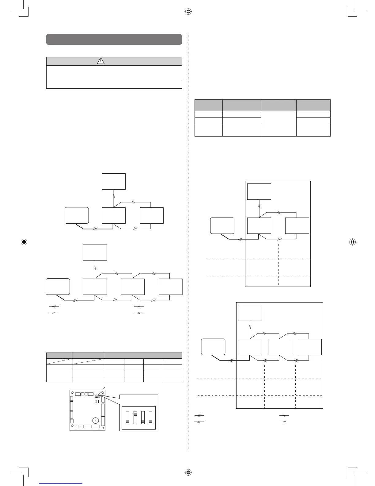
Twin type
Indoor
unit ①
(master)
Outdoor
unit
Indoor
unit ②
(slave)
Remote
controller
DIP switch setting
(Indoor unit)
• Unit number
• Setting value
(Master/Slave)
Remote controller
setting
• Unit number
00 01
00 01
00 01
Triple type
Indoor
unit ①
(master)
Outdoor
unit
Indoor
unit ②
(slave)
Remote
controller
Indoor
unit ③
(slave)
DIP switch setting
(Indoor unit)
• Unit number
Remote controller
setting
• Unit number
00 01
00 01
02
02
00 01 01
: Transmission cable, Power supply cable
: Remote controller cable : Bus wire
: Power supply cable
• Setting value
(Master/Slave)
9.4. Special installation methods
This possible only the wired remote control. (Option)
CAUTION
When setting DIP switches, do not touch any other parts •
on the circuit board directly with your bare hands.
Be sure to turn off the main power.•
9.4.1. Simultaneous multi-system operation
By combining with an outdoor unit, 2 units for twin and 3 units •
for triple indoor units, can be switched ON/OFF simultanne-
ously.
When different indoor unit models are connected some func-•
tions may no longer be available.
Wiring method(1)
Refer to 6.ELECTRICAL WIRING for wiring procedure and •
wiring method.
The indoor unit is connected the outdoor unit using a trans-•
mission cable is “master”.
Connect the remote controller wire to the master unit.•
Twin type
Indoor
unit ①
[master]
Outdoor
unit
Indoor
unit ②
[slave]
Remote
controller
Triple type
Indoor
unit ①
[master]
Outdoor
unit
Indoor
unit ②
[slave]
Remote
controller
Indoor
unit ③
[slave]
: Transmission cable, Power supply cable
: Remote controller cable : Bus wire
: Power supply cable
DIP switch setting (Indoor unit)(2)
Set the unit number of each indoor unit using the DIP
switches on the indoor unit circuit board. (See the follow-
ing table and fi gure.)
The DIP switches are normally set to make the unit
number 00.
Indoor unit Unit number
DIP SWITCH No.
1234
①
00 OFF OFF OFF OFF
②
01 ON OFF OFF OFF
③
02 OFF ON OFF OFF
DIP switches
ON
1234
Example :
Unit number 02
Circuit board in the control box of indoor unit.
NOTE
Be sure to set the unit numbers sequentially.