En-17
Indoor unit Unit number
Function
Number
Setting Value
①
00
02
00〜15
②
01
〜
〜
⑮
14
⑯
15
After completing the function settings, turn off all of the 3.
indoor units, and then turn them back on.
If error code 01, 1F, 30, 31, or 32 is displayed, there *
may be an incorrect setting. Perform the remote
controller setting again.
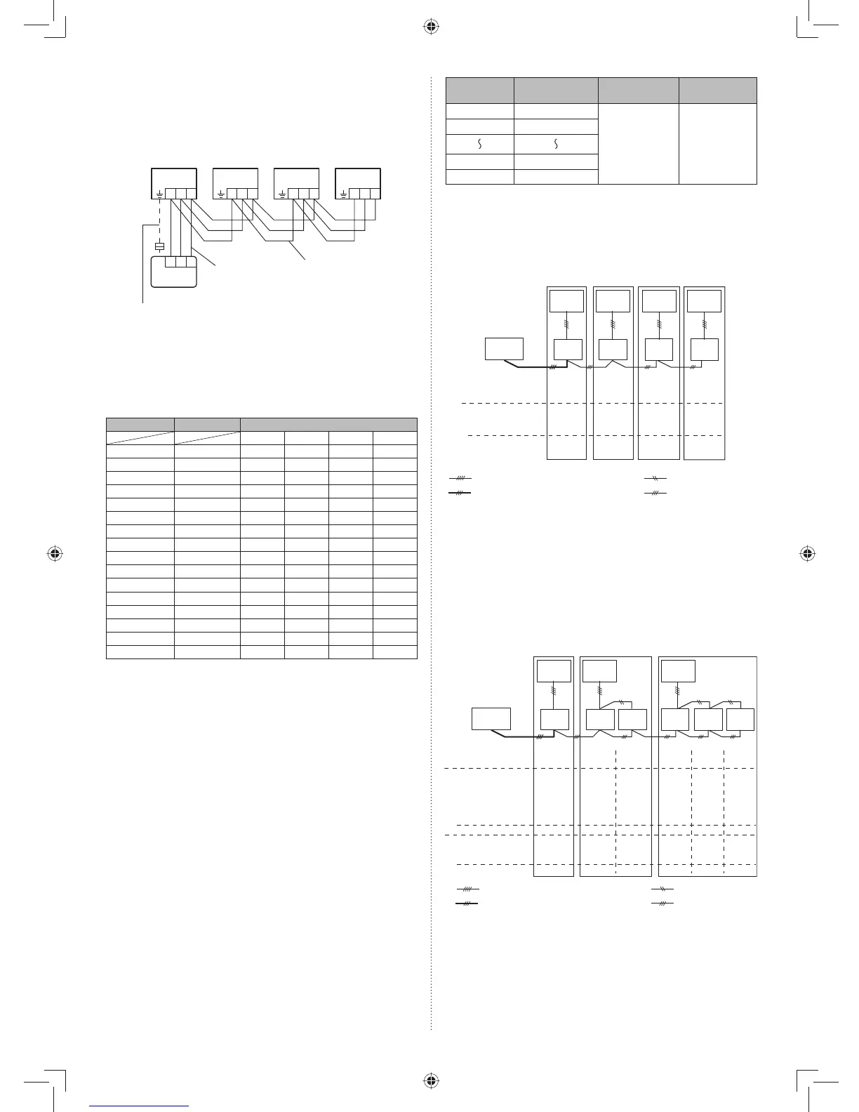
: Transmission cable, Power supply cable
: Remote controller cable : Bus wire
: Power supply cable
Remote
controller
Indoor
unit 1
Outdoor
unit 1
Indoor
unit 2
Outdoor
unit 2
Indoor
unit 3
Outdoor
unit 3
Indoor
unit 4
Outdoor
unit 4
00 01 02 03
00 01 02 03
00 01 02 03
DIP switch setting
(Indoor unit)
• Unit number
• Setting value
(Refrigerant circut
address)
Remote controller
setting
• Unit number
NOTE
When different indoor unit models are connected using the •
group control system, some functions may no longer be avail-
able.
If the group control system contains multiple units that are •
operated simultaneously, connect and set the units as shown
below.
Simultaneous
triple
Simultaneous
twin
Standard
pair
Remote
controller
Indoor
unit 1
Outdoor
unit 1
Indoor
unit 2
Indoor
unit 3
Outdoor
unit 2
Indoor
unit 4
Indoor
unit 5
Indoor
unit 6
Outdoor
unit 3
: Transmission cable, Power supply cable
: Remote controller cable : Bus wire
: Power supply cable
00 01 02 03 04 05
00
01 01 02 02 0200
01 02 03 04 05
00 00 01 00 01 01
00 01 02 03 04 05
DIP switch setting
(Indoor unit)
• Unit number
Remote controller
setting
Refrigerant circuit
address setting
(Function number 02)
• Unit number
• Setting value
Master/Slave setting
(Function number 51)
• Unit number
• Setting value
*Make sure that the indoor unit with the unit number 00 is
connected to the outdoor unit using a transmission cable.
9.4.2. Group control system
A number of indoor units can be operated at the same time
using a single remote controller.
(1) Wiring method (indoor unit to remote controller)
123
123
123 123 123
Indoor
unit ①
Indoor
unit ②
Indoor
unit ③
Indoor
unit ④
Bus wire
Remote
controller cable
When ground wire is necessary
Remote controller
DIP switch setting (Indoor unit)(2)
Set the unit number of each indoor unit using the DIP
switches on the indoor unit circuit board. (See the follow-
ing table and fi gure.)
The DIP switches are normally set to make the unit
number 00.
Indoor unit
Unit number
DIP SWITCH No.
1234
①
00 OFF OFF OFF OFF
②
01 ON OFF OFF OFF
③
02 OFF ON OFF OFF
④
03 ON ON OFF OFF
⑤
04 OFF OFF ON OFF
⑥
05 ON OFF ON OFF
⑦
06 OFF ON ON OFF
⑧
07 ON ON ON OFF
⑨
08 OFF OFF OFF ON
⑩
09 ON OFF OFF ON
⑪
10 OFF ON OFF ON
⑫
11 ON ON OFF ON
⑬
12 OFF OFF ON ON
⑭
13 ON OFF ON ON
⑮
14 OFF ON ON ON
⑯
15 ON ON ON ON
Turn on all of the indoor units.1.
*
1
Turn on the indoor unit with the unit number 00 last.
(Within 1 minute)
*
2
When the indoor units are turned on, error codes
01 and 31 will be displayed; however, these error
codes will be deleted by setting the remote controller.
Therefore, continue with the setting procedure.
Set the refrigerant circuit address. 2.
Assign the same number to all of the indoor units con-
nected to an outdoor unit.
(The unit is factory-set to “00”)