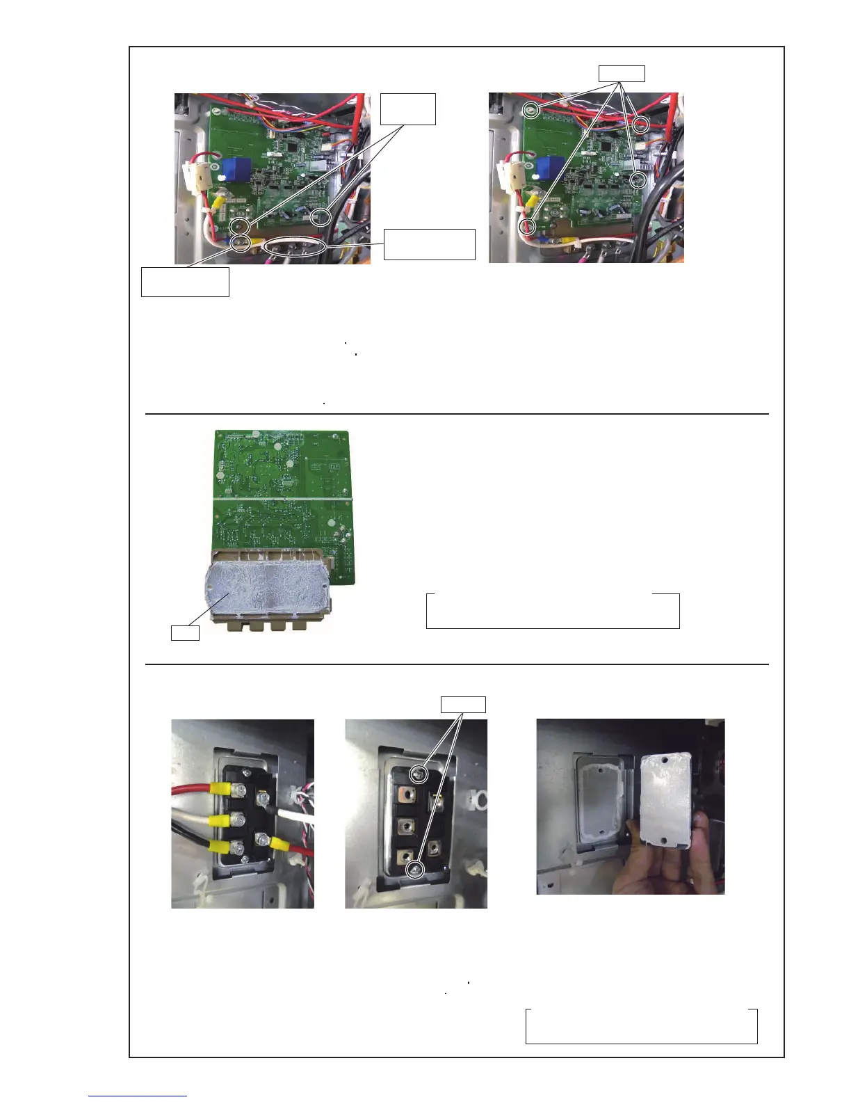
Remove the 4 mounting screws.
Remove the connectors and spacers.
Remove the wires. Remove the screws.
06-04
Screw
(To Power PCB)
Screws
(For IPM)
Spacers
Screws
5-2. INVERTER PCB removal
5-3. DIODE BRIDGE removal
Spread the heat transfer compound on IPM
when you exchange INVERTER PCB by the repair.
For screws of IPM.
Note the tightening torque at the installation.
Temporary tightening : 0.2 to 0.4N m
Final tightening : 0.98 to 1.47N m
Note at the installation.
1. Remove the old heat transfer compound as possible from IPM and
Diode Bridges when you exchange INVERTER PCB by the repair.
2. Spread the heat transfer c
o
mpound evenly on IPM and Diode Bridges.
3. Prevent foreign matter from attaching to the surface of IPM and Diode Bridges.
Note at the installation.
1. Remove the old heat transfer compound as possible from
D.B. when you
exchange ACTPM by the repair.
2. Spread the heat transfer compound evenly on D.B. .
3. Prevent foreign matter from attaching to the surface of D.B. .
For screws of D.B. .
- Manufacturer : Shin-Etsu Chemical Co.,Ltd
- Grade : G746
Specifications for the heat transfer compound
Spread the heat transfer compound on D.B.
when you exchange D.B. by the repair.
- Manufacturer : Shin-Etsu Chemical Co.,Ltd
- Grade : G746
Specifications for the heat transfer compound
IPM
Screws
(For Comp. Wire)
Note the tightening torque at the installation.
Tightening torque is as follows.
- Final tightening : 1.4 to 1.6 N m
For screws of Comp. Wire.
-
-
Note the tightening torque at the installation.
Tightening torque is as follows.
- Temporary tightening : 0.6 +0.1N m
- Final tightening : 2.4 +0.1N m