3
5. INSTALLING THE REMOTE CONTROLLER
5.1. Wiring
WARNING
%HIRUHVWDUWLQJLQVWDOODWLRQZRUNWXUQRIIWKHSRZHURIWKHFRQQHFWLRQ
destination. Do not turn on the power again until installation is completed.
2WKHUZLVHLWZLOOFDXVHHOHFWULFVKRFNRU¿UH
8VHWKHDFFHVVRULHVRUVSHFL¿HGFRQQHFWLRQFDEOHV
'RQRWPRGLI\FRQQHFWLRQFDEOHVRWKHUWKDQWKRVHVSHFL¿HGGRQRWXVH
H[WHQVLRQFRUGVDQGGRQRWXVHLQGHSHQGHQWEUDQFKZLULQJ7KHDOORZ
DEOHFXUUHQWZLOOEHH[FHHGHGDQGFDXVHHOHFWULFVKRFNRU¿UH
,QVWDOOWKHFRQQHFWLRQFDEOHVVHFXUHO\WRWKHWHUPLQDOEORFN&RQ¿UPWKDW
external force is not applied to the wire. Use connection cables made
RIWKHVSHFL¿HGZLUH,ILQWHUPHGLDWHFRQQHFWLRQRULQVHUWLRQ¿[LQJDUH
LPSHUIHFWLWZLOOFDXVHHOHFWULFVKRFN¿UHHWF
'RQRWFRQQHFWIXQFWLRQDOHDUWKLQJWRDWHOHSKRQHIXQFWLRQDOHDUWKLQJ
ZDWHUSLSHRUFRQGXFWRUURG
Always fasten the outside covering of the connection cable with the cable
FODPS,IWKHLQVXODWRULVFKDIHGHOHFWULFOHDNDJHPD\RFFXU
:KHQSHUIRUPLQJFDEOHZLULQJZRUNEHVXUHWKDWLWGRHVQRWWRXFKWKH
XVHU'RLQJVRZLOOFDXVHLQMXU\RUHOHFWULFVKRFN
,IDQ\FDEOHLVGDPDJHGGRQRWUHSDLURUPRGLI\LW\RXUVHOI,PSURSHUZRUN
ZLOOFDXVHHOHFWULFVKRFNRU¿UH
CAUTION
'RQRWSDUDOOHOWRWKHUHPRWHFRQWUROOHUFDEOHVLQGRRUDQGRXWGRRU
FRQQHFWLRQFDEOHDQGSRZHUVXSSO\FDEOHV,WPD\FDXVHHUURQHRXV
operation.
:KHQSHUIRUPLQJZLULQJZRUNEHFDUHIXOQRWWRGDPDJHWKHFDEOHRU
LQMXUH\RXUVHOI$OVRFRQQHFWWKHFRQQHFWRUVVHFXUHO\/RRVHFRQQHFWRUV
ZLOOFDXVHWURXEOHKHDWLQJ¿UHRUHOHFWULFVKRFN
Install the remote control cable 1 m away from television and radio to
avoid distorted images and noise.
Perform wiring so that water does not enter this unit along the external
wiring. Always install a trap to the wiring or take other countermeasures.
2WKHUZLVHLWZLOOFDXVHWURXEOHRUHOHFWULFVKRFNRU¿UH
&RQ¿UPWKHQDPHRIHDFKXQLWDQGQDPHRIHDFKWHUPLQDOEORFNRIWKH
unit and connect the wiring in accordance with the directions given in the
manual so that there is no incorrect wiring. Incorrect wiring will damage
WKHHOHFWULFSDUWVDQGFDXVHVPRNHDQG¿UH
When installing the connection cable near a source of electromagnetic
ZDYHVXVHVKLHOGHGFDEOH2WKHUZLVHDEUHDNGRZQRUPDOIXQFWLRQFRXOG
result.
5.2. Connection of remote controller cable
CAUTION
When connecting the remote controller cable to the wall mounted type
DQGWKHÀRRUW\SHLQGRRUXQLWGRQRWFRQQHFWLWWRWKHRXWGRRUXQLWRUWKH
indoor unit power terminal block. It may cause a failure.
There are 2 methods to connect the remote controller cable to the indoor
unit. One is the connection using contained connecting cable and the other
is the connection the remote controller cable is connected to the exclusive
terminal block of the indoor unit. Modify the remote controller cable as per
below description and connect it.
Exclusive terminal block for remote controller connection method is different
depending on each model.
)RUWKHGHWDLOVUHIHUWRWKHLQVWDOODWLRQPDQXDORIWKHLQGRRUXQLWWREHXVHG
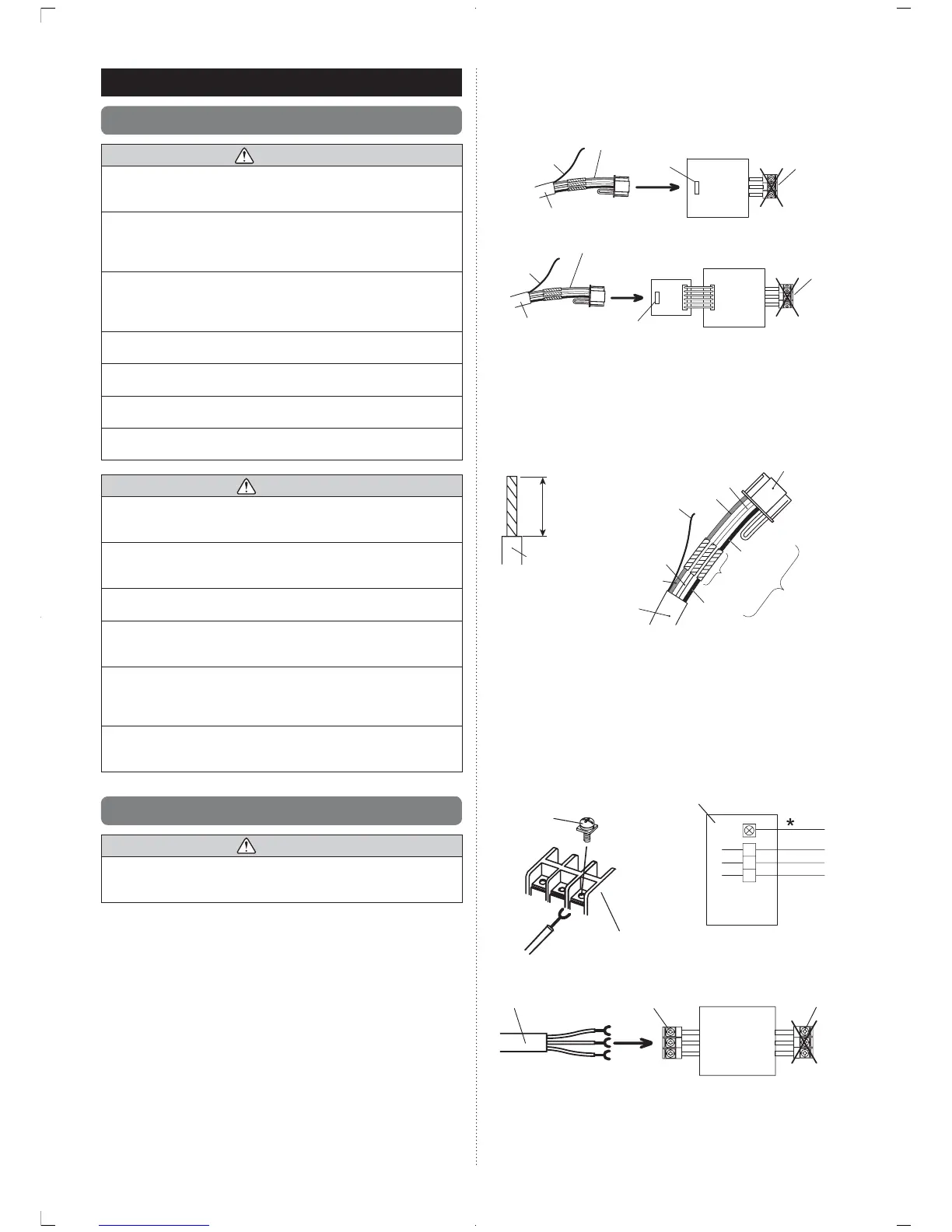
5.2.1 When connecting to the wall mounted type
DQGWKHÀRRUW\SHFRQQHFWRU
&RQQHFWWKHUHPRWHFRQWUROOHUFDEOH¿HOGVXSSO\WRWKHFRQQHFWLQJFDEOH
and insert it to the connector.
PCB
Connecting cable
Remote controller
cable (field supply)
Indoor unit
Outdoor
unit /
power
supply
terminal
block
Connector
Remote controller
cable (field supply)
Outdoo
unit /
power
supply
terminal
block
Indoor unit
PCB
Connector
Connecting cable
Communication
kit (option)
Pattern 1
Pattern 2
Functional
earthing
Wire
Functional
earthing
Wire
Modify the cable as per below methods.
(1) Use a tool to cut off the terminal on the end of the remote controller cable
and then remove the insulation from the cut end of the wire as shown in
Fig. 1.
(2) Connect the remote controller cable and connecting cable as shown in
Fig. 2.
(3) Be sure to insulate the connection between the cables.
Connecting
cable
Connector
Fig. 1 Fig. 2
White
Red
White
Red
Black
Black
Insulated
connection
Remote
controller cable
Wire
20 mm
Functional
earthing
Wire
Always perform the wire insulation on the functional earthing wire of the
remote controller cable.
Attach the functional earthing wire in the cable to the Indoor electronic
control unit with the screw (small). The position of the screw hole varies
by model.
5.2.2 When connecting to the exclusive terminal
block
Connect the end of remote controller cable directly to the exclusive terminal
block.
Terminal block
M4 screw
3
2
1
Black
White
Red
* functional earthing wire
Indoor unit or zone-control-
interface
PCB
Indoor unit
Outdoor unit /
power supply
terminal bl
 Loading...