6
When routing the cable on top of the front case:
Seal the cable guide of the front case of the remote controller cable with
an epoxy putty.
Thickness of sheath of the remote controller cable should be thicker
than 1 mm or more. Or insulate it with a cable cover thicker than 1 mm
or more.
Epoxy putty
Cable cover
6. INSTALLATION METHODS
6.1.
Installation methods without zone control
6.1.1 Group control
A number of indoor units can be operated at the same time using a single
remote controller.
'HSHQGLQJRQWKHPRGHOVRPHLQGRRUXQLWVFDQQRWEHFRQQHFWHGIRU
JURXSFRQWURO*URXSFRQWUROLVDYDLODEOHIRUWKHGXFWW\SHWKHFDVVHWWH
W\SHDQGWKHFHLOLQJW\SHLQGRRUXQLW
6RPHIXQFWLRQVPD\EHFRPHXQXVDEOHGHSHQGLQJRQWKHFRPELQDWLRQRI
the indoor units that are connected in a group.
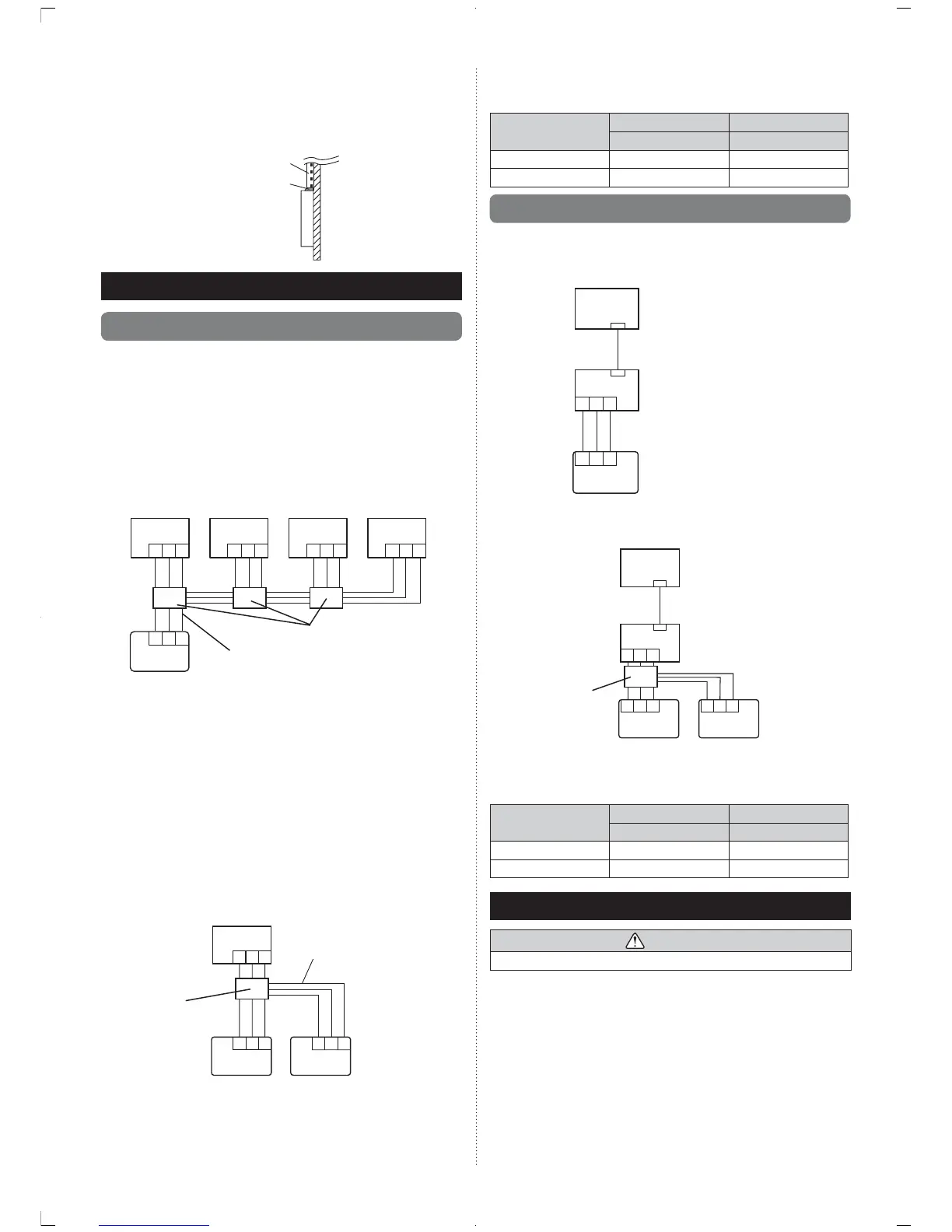
(1) Wiring method (indoor unit to remote controller)
EXAMPLE: Single Type
123
123
123 123 123
Indoor unit 0 Indoor unit 1 Indoor unit 2 Indoor unit 3
Remote controller
cable
Remote controller
Junction box
¿HOGVXSSO\
(2) Indoor unit address setting
Set each indoor unit address using the DIP switch of each indoor unit.
(Refer to the installation manual for the indoor unit.)
6.1.2 Dual remote controllers
Field setting can be performed only on the primary unit.
Assignment of primary unit and secondary unit is necessary. No assign
ment will cause an error.
'HSHQGLQJRQWKHPRGHOVRPHLQGRRUXQLWVFDQQRWEHFRQQHFWHGIRUGXDO
UHPRWHFRQWUROOHUV'XDOUHPRWHFRQWUROOHUVDUHDYDLODEOHIRUWKHGXFWW\SH
the cassette type and the ceiling type indoor unit.)
Two separate remote controllers can be used to operate the indoor units.
The timer and functions cannot be used on the secondary units. (For the
GHWDLOVUHIHUWRWKHRSHUDWLQJPDQXDO
(1) Wiring method (indoor unit to remote controller)
1 231 23
1 2 3
Indoor unit
Remote controller cable
Primary unit
Secondary unit
Remote controller
Junction box
¿HOGVXSSO\
(2) Remote controller DIP switch 1 setting
Set the remote controller DIP switch No. 2 according to the following
table.
Number of remote
controllers
Primary unit Secondary unit
DIP Switch No. 2 DIP Switch No. 2
1 (Normal) OFF –
2 (Dual) OFF ON
6.2. Installation methods with zone control
,QVWDOOLQJ]RQHFRQWUROLQWHUIDFHHQDEOHV]RQHFRQWUROV\VWHP
6.2.1 Single remote controller
:LULQJPHWKRG]RQHFRQWUROLQWHUIDFHWRUHPRWHFRQWUROOHU
Remote controller
Indoor unit
=RQH&RQWURO,QWHUIDFH
123
123
6.2.2 Dual remote controllers
:LULQJPHWKRG]RQHFRQWUROLQWHUIDFHWRUHPRWHFRQWUROOHU
Remote controller
Indoor unit
=RQH&RQWURO,QWHUIDFH
123 123
123
Primary unit
Secondary unit
Junction box
¿HOGVXSSO\
(2) Remote controller DIP switch 1 setting
Set the remote controller DIP switch No. 2 according to the following
table.
Number of remote
controllers
Primary unit Secondary unit
DIP Switch No. 2 DIP Switch No. 2
1 (Normal) OFF –
2 (Dual) OFF ON
7. TURNING ON THE POWER
CAUTION
Recheck the wiring. Incorrect wiring will cause trouble.
(1) Check the remote controller wiring and DIP switch settings.
(2) Install the front case.
(in 5. INSTALLING THE REMOTE CONTROLLER).
(3) &KHFNWKHLQGRRUXQLWRXWGRRUXQLWDQG]RQHFRQWUROLQWHUIDFHZLULQJDQG
FLUFXLWERDUGVZLWFKVHWWLQJVDQGWKHQWXUQRQWKHLQGRRUDQGRXWGRRU
units. After message “Please wait” is displayed on the remote control
OHUGLVSOD\³/DQJXDJH´VFUHHQLVGLVSOD\HG,Q]RQHFRQWUROOHGV\VWHP
"Number of outlets" screen is displayed.
 Loading...