- 14 -
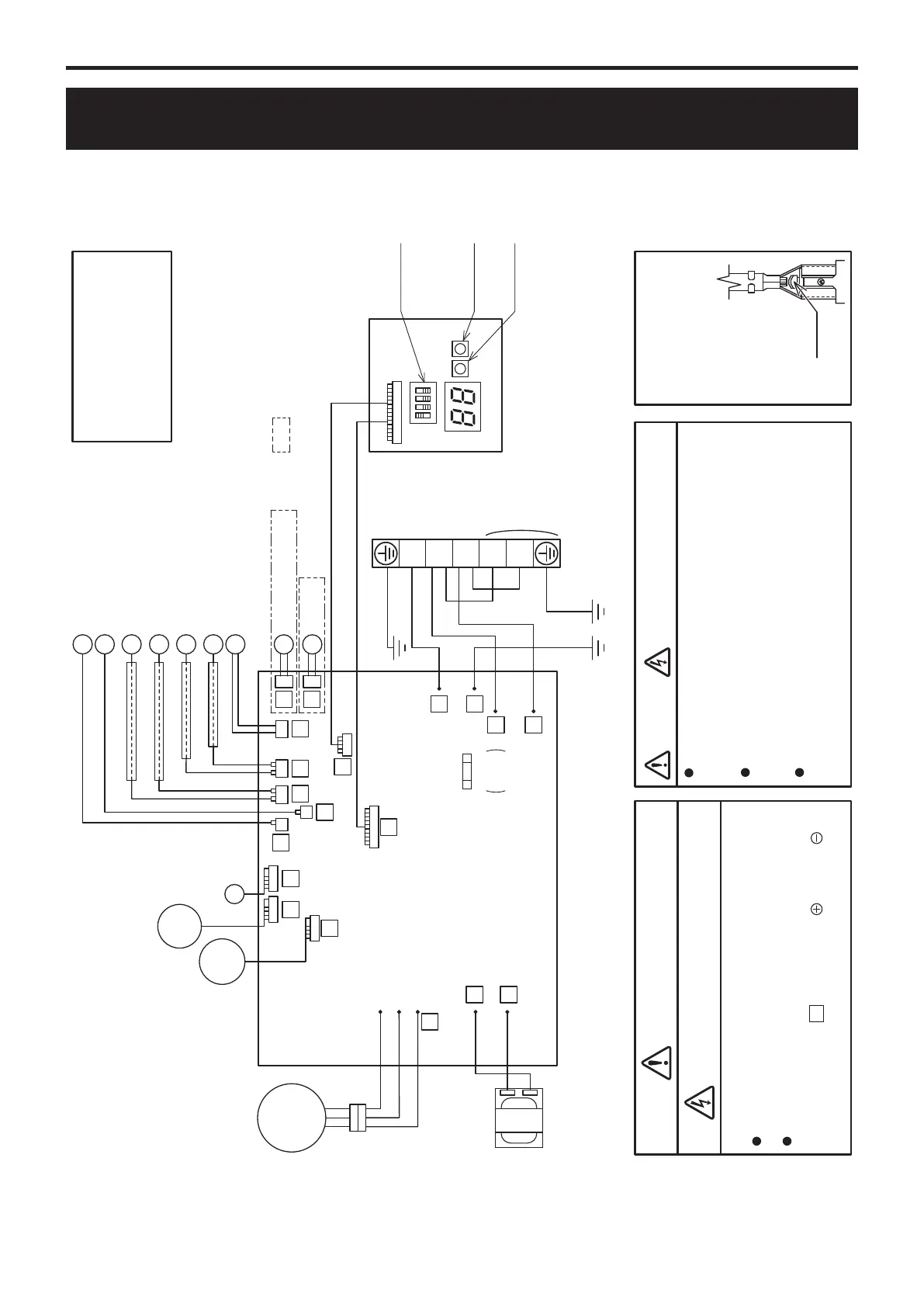
WIRING DIAGRAM
TROUBLESHOOTING GUIDE
COMPRESSOR
U
(R)
V
(S)
W
(T)
R
BL
R
B
WW
BB
BB
W
B
W(T)
V(S)
U(R)
7
6
5
OR
Y
※ ※
REACTOR
FUSE
250V
T3.15A
14
MOTOR
(FAN)
PUMP
13
EXP.V.
28
31
33
23
22
21 19 8
9
10
PCB(DISPLAY)
PCB
(CONTROLLER)
SENSOR(TEMP.,SUCTION)
SENSOR(TEMP.,DEFROST)
SENSOR(TEMP.,DISCHARGE)
SENSOR(TEMP.,OUTDOOR)
SENSOR(TEMP.,OUTGOING)
4WAYV.
DEFROSTHEATER
HEATER
SENSOR(TEMP.,RETURN)
MODESW.
RESETSW.
PUMPSW.
:Notavailableforthemodel
withoutdefrostheater
ON
OFF
Warningwhenyoufixelectriccomponents!
ElectricShock!
Don'ttouchelectricallychargedparts,aselectricshock
mayoccureveniftheyareswitchedoff.
WARNING!
Donottouchanypartoftheelectriccircuit
(includingthewiringofthermistorandothers),
asithashighvoltageagainsttheground.
Payattentionnottodamagetheinsulatedwire
whenyoutightenthescrew,astheexposedwire
maycauseelectricshockormalfunction.
Donotgroundtheoscilloscopewhenyouoperate.
Youmightdestroyit.Alsodonottouchanymetal
partoftheoscilloscopewhileoperating.
Howtorelease
lockingterminals(※)
Lever
Toreleasethe
terminals(※),
pressthelocking
leverandpull.
Caution ElectricShock HighVoltage
R:RED
G:GREEN
GR :GRAY
OR :ORANGE
Y:YELLOW
B:BLACK
W:WHITE
BL:BLUE
COLOROFWIRE
B
W
B
W
R
W
B
GR
G/Y
G/Y
※
※
※
※
※
※
※
※
※
3
4
2
1
TERMINAL
BLOCK
N
L
POWER
1
2
3
Besuretowaitatleast5min.afterturningoffthepower
andtoconfirmthevoltagebetweentheconnectorpins
ofpumpconnector13[betweenwhite
andblack
]
islessthanDC10Vwithatesterbeforeservicing.