Questions? Please Contact Your Local Manufacturer’s Representative
SECTION 2 EDR-SOLA-IOM-2022-0216 INSTALLATION
2-5
Clearances and Serviceability
Adhere to the following for clearances and serviceability:
1. All local and national codes (NFPA, ANSI, UL, CSA,
ASME) must be followed for proper clearances and
serviceability of your boiler. Authorities having
jurisdiction should be consulted before installations are
made.
2. Appropriate front, back, side and top clearances must
be maintained (Figure 1). This will allow access around
the equipment to facilitate maintenance and a safe
work environment. A 1-inch (25.4 mm) side clearance
is acceptable between any number of boilers. Custom
congurations may not allow 1-inch (25.4 mm) side
clearance. Although a 1 inch (25.4 mm) side clearance
is permitted, allowing 24 inches (610 mm) will
facilitate and expedite maintenance and any advanced
troubleshooting.
NOTE: Side panels are latched; however, maintenance and
service does not require boiler access through side panels. All
maintenance and service can be performed from front, rear,
and top of boiler.
3. Ensure all labels on the boiler will be fully visible for
maintenance and inspection.
4. Do not place any boiler room accessories, or other
components, on the Endura skid.
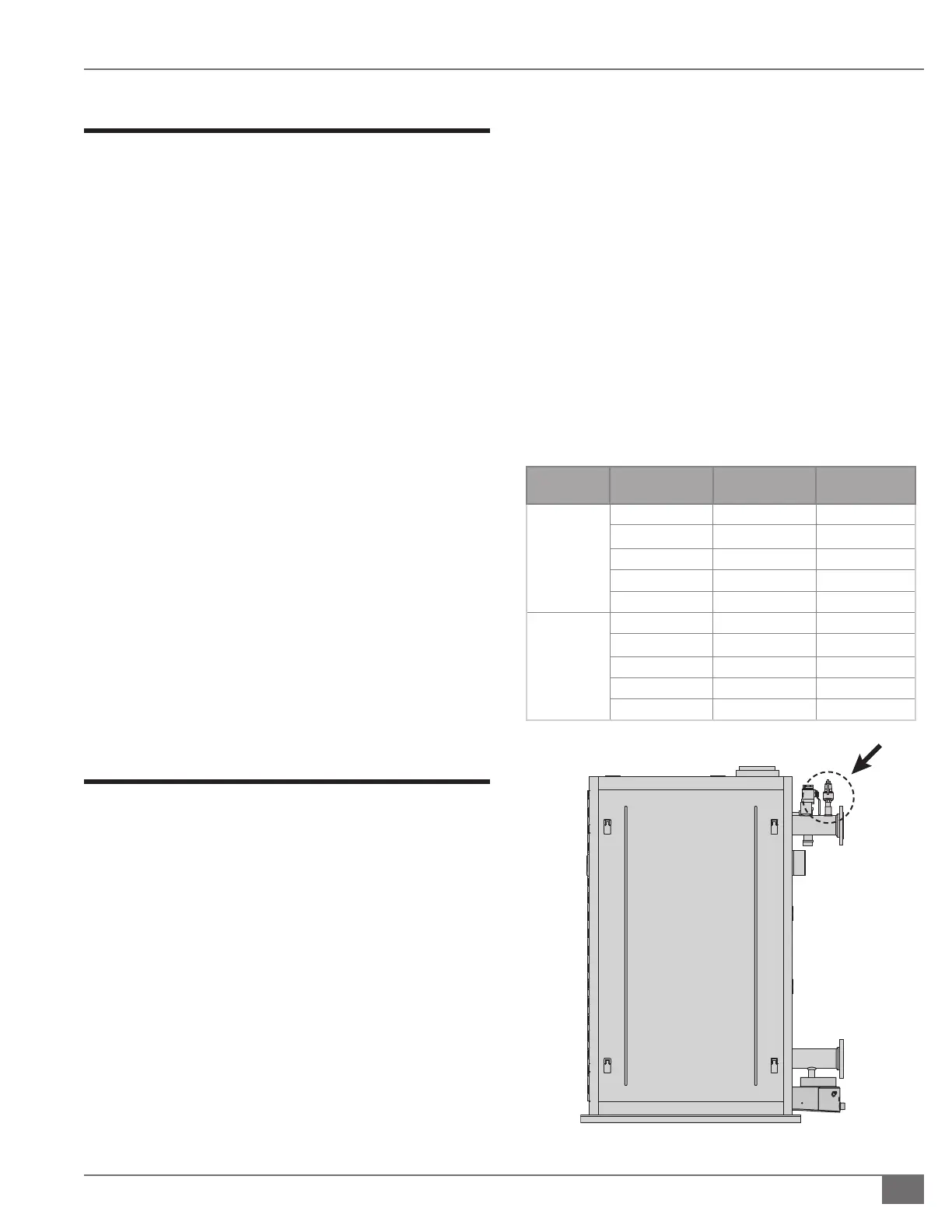
Install Boiler Trim
Each Endura boiler is supplied with a safety relief valve sized
in accordance with ASME requirements. Adhere to the
following installation requirements:
1. The safety relief valve (Figure 2) must:
» Be connected to the coupling located in the
top of the boiler.
» Be installed in the upright vertical position.
NOTE: Safety relief valve size is determined by trim pressure
and is supplied in the trim kit along with appropriate bushing,
inlet and outlet sizes. See Table 2. Standard trim pressure is 60
PSIG.
2. The discharge pipe must:
» Not have a diameter less than the full area of
the valve outlet.
» Be as short and straight as possible and so
arranged as to avoid undue stress on the valve.
» Be supported by means other than the safety
valve itself.
» Be piped to avoid danger of scalding
personnel.
NOTE: Each boiler is equipped with a pressure-temperature
gauge to be installed in the outlet piping section of the boiler.
Gauge must not be isolated from the boiler by any valve.
TABLE 2 SAFETY RELIEF VALVE INLET AND OUTLET SIZES
Model
Trim Pressure PSI
(kPa)
Inlet Size
inch (mm)
Outlet Size inch
(mm)
EDR-750
EDR-1000
EDR-1500
30 (206.84) 1 (25.4) 1 1/4 (31.75)
60 (413.69) 3/4 (19.05) 1 (25.4)
100 (689.48) 3/4 (19.05) 1 (25.4)
125 (861.84) 3/4 (19.05) 1 (25.4)
160 (1103.16) 3/4 (19.05) 1 (25.4)
EDR-2000
30 (206.84) 1 1/4 (31.75) 1 1/2 (38.1)
60 (413.69) 1 (25.4) 1 1/4 (31.75)
100 (689.48) 3/4 (19.05) 1 (25.4)
125 (861.84) 3/4 (19.05) 1 (25.4)
160 (1103.16) 3/4 (19.05) 1 (25.4)
Note: Valve is
shipped loose
and must be
installed by the
contractor.
FIGURE 2 SAFETY VALVE LOCATION
 Loading...