Questions? Please Contact Your Local Manufacturer’s Representative
2-7
SECTION 2 EDR-SOLA-IOM-2022-0216 INSTALLATION
! WARNING
All information in this manual is for
reference and guidance purposes,
and does not substitute for required
professional training, conduct,
and strict adherence to applicable
jurisdictional/professional codes and
regulations.
Ensure all labels on the boiler are
legible. All connections and safety
devices, both mechanical and
electrical, must be kept clean, with
ease of access for inspection, use and
maintenance.
Do not store or use gasoline or other
ammable vapors and liquids or
corrosive materials in the vicinity of
this or any other appliances.
Install bypass chemical feeder for corrosion inhibitor maintenance if
appropriate.
Install corrosion coupon holder to assess corrosion inhibitor performance if
appropriate.
Before installing into a hydronic loop, be sure that the system piping and
any other components of the system are clean and free of debris and any
foreign matter. The hydronic system must be completely ushed prior to
installing the boiler.
Variable Primary Piping Arrangement
The boiler is designed for installation in variable primary ow piping
arrangements (see Figures 4 and 5), sometimes referred to as full ow systems.
This arrangement eliminates temperature mixing associated with primary-
secondary piping, thereby delivering the lowest temperature water directly
to the boiler return connections and increasing thermal eciency of the
condensing boiler plant.
Adhere to the following for variable primary piping arrangements:
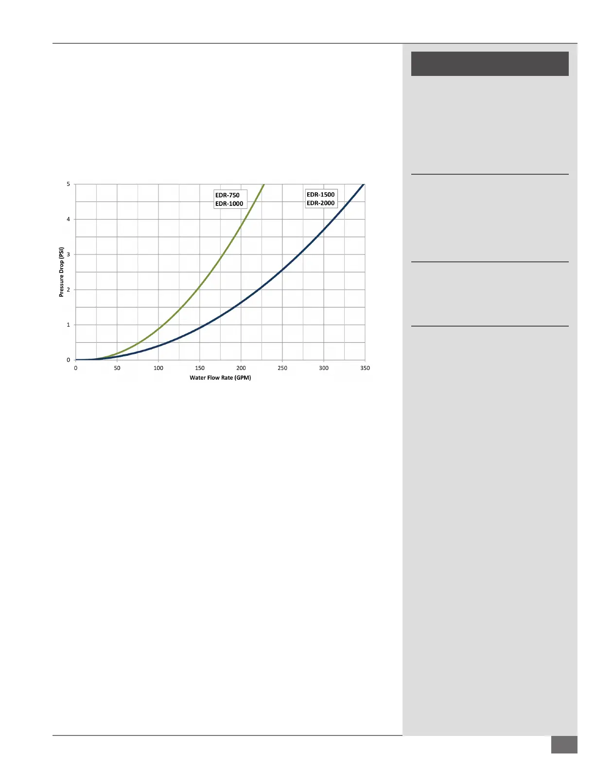
Select secondary (system) pump(s) with sucient total dynamic head for
the pressure drop of the loop at design ow. See Figure 3 for the boiler
water pressure drop. This boiler will automatically perform a safe shutdown
in the event of a low ow condition; however, proper design ow is
required to deliver heat to the users and prevent nuisance lockouts.
Install a motorized isolation valve per boiler. This eliminates ow through
idle boilers accordance with ASHRAE 90.1-2013 (6.5.4.3.2). Blending of
unheated supply water impacts temperature control and can cause
manual reset high temperature lockouts. Use only one motorized isolation
valve per boiler; two-position type actuator, open or closed. It is acceptable
to install the valve on either the inlet or the outlet piping of each boiler, but
never both. Select a valve with a cycle time of 45 seconds or less. Do not
install modulating isolation valves on boiler piping.
FIGURE 3 TYPICAL WATER SIDE PRESSURE DROP
 Loading...