© Fulton Group N.A., Inc. 2022
INSTALLATION EDR-SOLA-IOM-2022-0216 SECTION 2
2-16
Components Requiring Ventilation to the
Outdoors
The following do not require ventilation to the outdoors, as
there is a vent limiter in use:
Lock-up regulator on the main fuel train
Regulator on the ignition enrichment line
An authority having jurisdiction (AHJ) may not permit the
use of a vent limiter on some or all components. If venting is
required, use the following general guidelines:
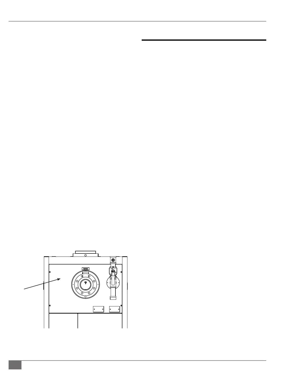
Drill an appropriately sized penetration for each vent
line through the topmost panel on the rear of the boiler
cabinet (Figure 12). Do not install any vent lines through
removable latching panels. Properly seal around the
pipe with silicone to maintain a sealed cabinet and
ensure combustion air will not bypass the lter.
Each component must have a separate vent line to
the outdoors. Vent lines must not be manifolded or
combined with any other vent or exhaust systems.
Start with the vent connection size and as soon as it is
practical, increase the pipe size one diameter. For every
ten feet of vent, increase the pipe size one diameter.
Never reduce the vent size.
Protect the vent termination from debris, dust and
insects. Install the vent termination above the snow
line and point down to prevent ingress of water. The
termination must be a minium of 3 ft (0.9 m) from a
source of ignition.
Install Condensate Drain Trap
A condensate drain trap is intended for use with the Fulton
Endura boiler.
Single Boiler Drain Trap
The single boiler condensate drain trap is Fulton Part Number
4-57-005500. The drain trap must be congured one per
boiler, with a maximum of 4.0 mm BTU total. (See Figures 13
and 15).
Adhere to the following for installation:
1. The 1 inch (25.4 mm) condensate drain will be reduced
and connected to the 3/4 inch (19.05 mm) inlet on the
base of the drain trap.
2. A condensate collecting tank and condensate pump
will be required if a oor drain is not available to collect
condensate (collecting tank and pump are not supplied
with the boiler).
3. All piping (Figure 13) must be CPVC, galvanized, or
stainless steel, and be free of leaks. Copper, carbon
steel/iron pipe, or PVC are not acceptable.
4. The drain trap must be installed below the boiler
condensate drain outlet.
5. Connect the 3/4 inch (19.05 mm) trap outlet to an
appropriate waste line following applicable codes. The
3/4 inch (19.05 mm) drain connection on the drain tank
must be the highest point prior to going to the drain.
Failure to keep drain piping lower than this point will
result in overow of the drain tank. Slope the drain pipe
away at a minimum pitch of 1 inch (25.4 mm) for every
12 feet (3.65 m).
NOTE: Ensure piping will not be exposed to freezing
temperatures.
FIGURE 12 TOPMOST REAR PANEL
When required,
run the vent
line(s) through
this panel
 Loading...