Questions? Please Contact Your Local Manufacturer’s Representative
SECTION 2 EDR-SOLA-IOM-2022-0216 INSTALLATION
2-29
Common Flue Gas Venting Layouts
It is possible to combine the air intake and/or exhaust
venting of multiple Endura boilers. The pressure drop across
the entire common system, the combined total of both air
intake and exhaust, must comply with the draft pressure
requirements for an individual boiler, see Table 4.
Refer to Figure 20 and adhere to the following for installation:
1. Consult your venting supplier for guidance in designing
common vented installations. The system must be
thoroughly evaluated by a professional using accepted
engineering practices to prevent backow of exhaust
gases through idle boilers.
2. This boiler is not approved for common venting with
other equipment, such as steam boilers, water heaters,
generators, and other types of equipment.
3. The AHJ may require the installation of a CO detector
interlocked with the boiler(s), this is recommended best
practice even where not required.
4. A constant diameter common header is recommended.
Do not use the static regain method.
5. A minimum 1/4” rise per foot run is required for
horizontal sections.
6. Where individual stacks transition into the common
header, a 45 degree reducing tee or elbow in the
direction of ow is recommended. Straight-in or 90
degree tees must not be used.
7. Precautions must be taken to ensure that the draft
pressure at each boiler is maintained within in the
required range (refer to Table 4) throughout all
conditions while also maintaining a slight negative
draft pressure in the common exhaust header. Consider
all possible operating conditions of the exhaust system
specic to the application, including:
Low and high ue gas temperatures
Low and high ambient air temperatures
All boilers operating at their maximum input
rating capacity
One boiler in the system operating at the low re
position
No boilers on, pre-purge and ignition
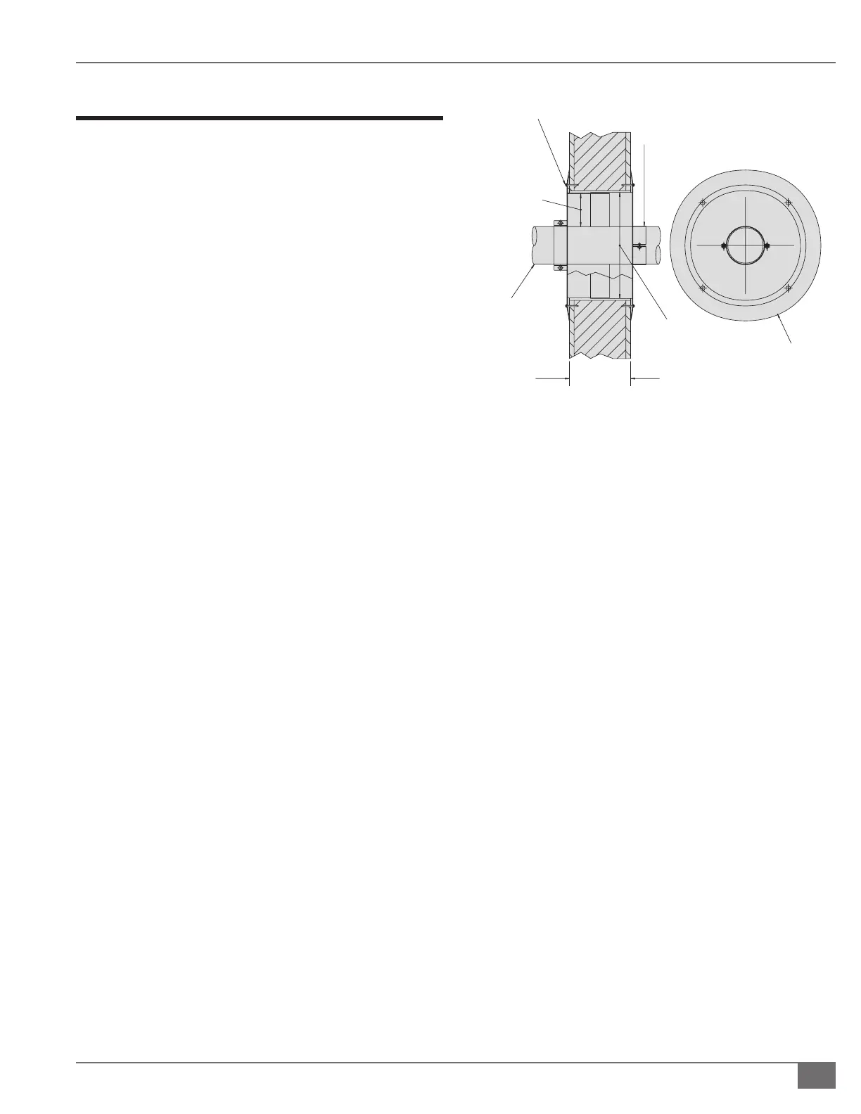
FIGURE 21 WALL THIMBLE INSTALLATION
VARIABLE
(MIN. 3 ¼ IN) – (MAX. 20 INCHES)
(MIN. 8,255 CM – MAX. 50,8 CM)
SCREW OR BOLT EACH THIMBLE COLLAR TO WALL
(TYPICAL 4 PLACES)
ORIENT CLAMPS AND COLLAR AS REQUIRED
PIPE RETAINING
CLAMP, TYPICAL
EACH SIDE
3½ INCH OR
4.35 CM AIR GAP
ALL AROUND
THRU PIPE
DIAMETER “C”
STAINLESS
DIAMETER “B”
ADJUSTABLE
WALL THIMBLE
WIDTH TO VARY WITH
WALL THICKNESS
DIAMETER “A” COLLAR
END VIEW
8. Consider the natural draft eects associated with vertical
exhaust vent rise. Over-draft control accessories, such
as modulating stainless steel dampers, may be required
to mitigate a negative pressure exceeding the value in
Table 4. An undersized common exhaust vent or pressure
drop due to the horizontal run can create a positive
pressure common exhaust situation which may require a
mechanical draft assist (exhaust fan) system.
When designing a draft system for a quantity of two or
more boilers, the following items must be considered and
addressed by the parties responsible for designing and
providing that system:
Common Venting Exhaust Backflow Prevention
1. When combining the exhaust vents of multiple Endura
boilers, the system must be designed to guarantee
ue gas and exhaust will not backow through an idle
boiler. This requires appropriately sizing a Category II
common exhaust vent to maintain a slight negative
draft pressure of -0.01 to -0.04”wc throughout all
operating conditions when one or more boilers are idle..
2. It is recommended to install individually piped intake
vents or use neutral pressure boiler room air with a
common exhaust system. For common exhaust vent
applications also combining combustion air intake (CAI)
ducts into a common duct, it is necessary to upsize the
common CAI duct for a negligible pressure loss.
3. If the common exhaust conguration does not allow
for a stable negative pressure under all operating
conditions then a mechanical draft assist system, such
as a variable speed exhaust fan, may be required.
 Loading...