Questions? Please Contact Your Local Manufacturer’s Representative
SECTION 2 EDR-SOLA-IOM-2022-0216 INSTALLATION
2-41
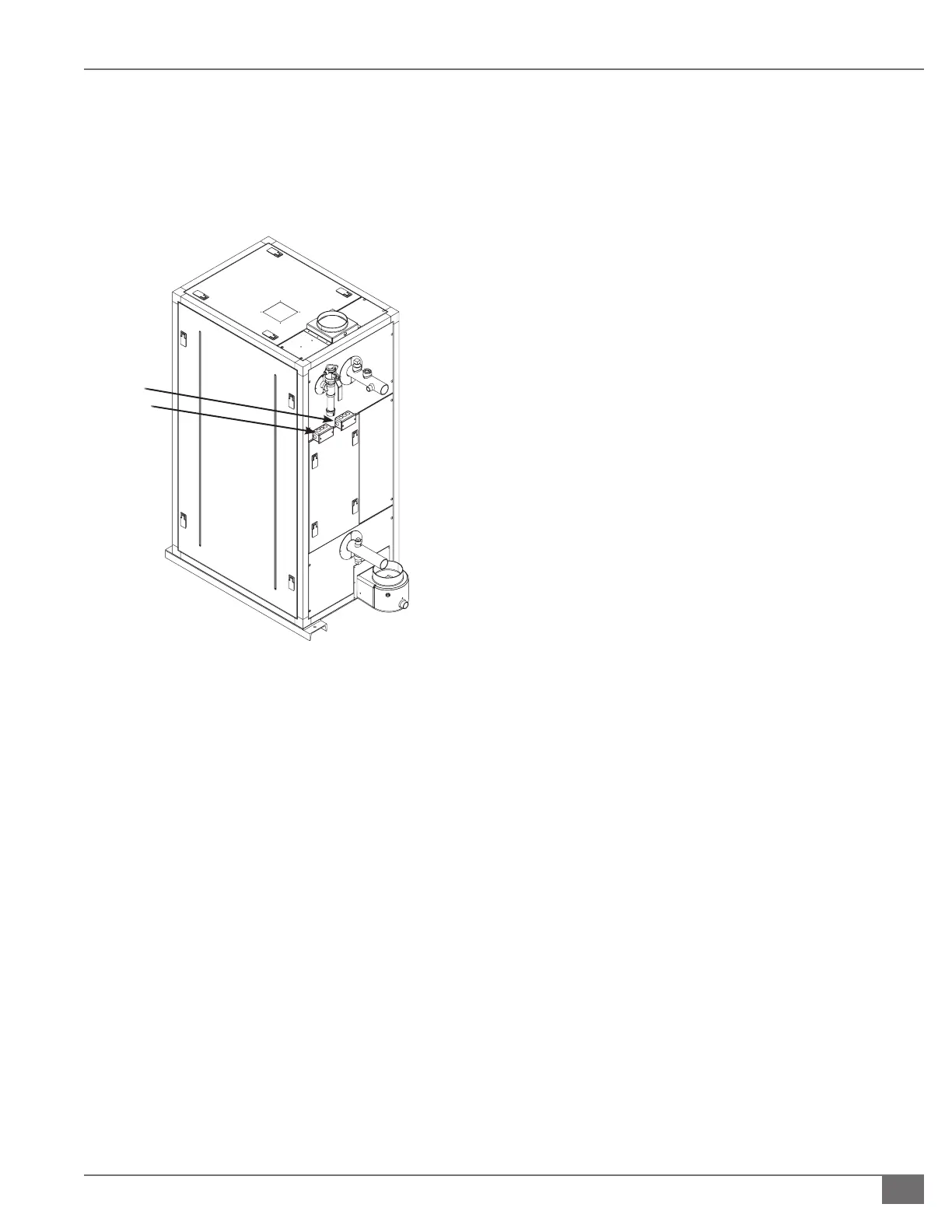
Junction Box Locations for Field Wiring
Factory mounted junction boxes (Figure 26) are provided
at the rear of the boiler for routing eld wiring to the boiler
control panel. Do not run wiring directly through the
removable or hinged panels doors.
FIGURE 26 LINE VOLTAGE AND LOW VOLTAGE
JUNCTION BOX LOCATIONS TYPICAL
Electrical and Controls Options
The electrical and controls options required and supplied
will vary depending on the unique requirements and
piping arrangements of the hydronic system. See Electrical
Schematic Diagrams for locations of eld wiring connections
on the below electrical devices and controls options.
The rating of each external device contact is the maximum
allowable amperage of the contact. The total Full Load Amps
(FLA) of external devices wired to the Endura boiler power
circuit cannot exceed 1A.
` LEAD/LAG INTEGRATED SEQUENCING WIRING
1. The Fulton SOLA includes integrated sequencing
capabilities. When utilized, the boiler control system will
automatically cascade boilers and operate burner ring
rates in parallel as necessary to maintain a hydronic
setpoint.
2. One boiler will be designated as the MASTER, with the
capability to cascade up to seven additional stages for
a maximum of eight boilers. The lead boiler, or the rst
to operate upon a call for heat, is automatically rotated
based on boiler run hours.
3. The supply header temperature sensor must be
utilized and wired to the MASTER boiler and installed
downstream of the boilers in the common supply water
header for proper operation of the sequenced plant.
4. Additional devices and sensors may be required, and
will vary by application.
5. Communication between the MASTER and additional
boilers is performed using the Modbus protocol.
This requires shielded, three-wire twisted pair
communication wire, Belden 3106A or equivalent.
Shield should only be grounded at one end and tied
directly to Earth ground.
6. See the Operation section for information on
programming this feature.
` INTEGRATION WITH THE MODSYNC SEQUENCING SYSTEM
Reference the User Manual and Electrical Schematic for the
ModSync Sequencing System. Communication requires
shielded three wire twisted Belden 3106A or equivalent.
Shield must be grounded at one end only and tied directly to
Earth ground.
` SUPPLER HEADER TEMPERATURE SENSOR
1. A hydronic supply sensor and
1/2
” NPT well (P/N 4-30-
000405) is used for temperature control.
2. This sensor is required for any multiple boiler
installation utilizing the integrated sequencing (lead/
lag) capabilities of the Fulton SOLA.
3. This sensor is required for single boiler installations with
primary-secondary piping arrangements to monitor the
primary loop.
4. The sensor monitors hydronic loop temperature in
the common supply piping as a process variable for
sequencing and modulation purposes. The control
uses this information when comparing actual loop
temperature to setpoint.
Electrical
Connections
 Loading...