Questions? Please Contact Your Local Manufacturer’s Representative
3-21
SECTION 3 EDR-SOLA-IOM-2022-0216 OPERATION
! WARNING
All information in this manual is for
reference and guidance purposes,
and does not substitute for required
professional training, conduct,
and strict adherence to applicable
jurisdictional/professional codes and
regulations.
Non-Fulton product information is for
reference purposes only. No Fulton
document may substitute for full
review of documentation available
from the component manufacturer.
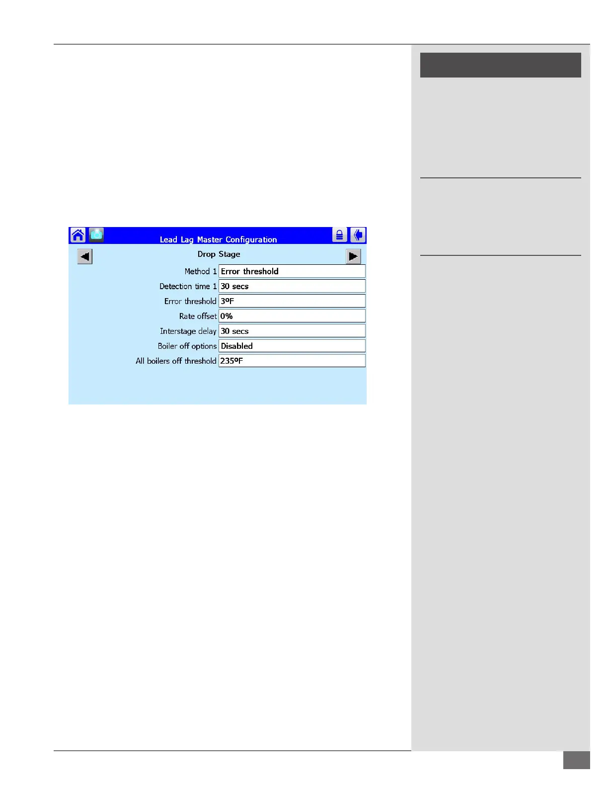
From the Lead Lag Master Conguration screen Select the box labeled Advanced
Settings in the bottom right hand corner. Use the left and right arrows to scroll to
the screen labeled drop stage. The row labeled Method 1 needs to be set to error
threshold. Refer to Figure 54 for factory default settings:
Interstage delay: The amount of time that must expire before the detection
begins.
Detection Time: The amount of time that must expire, after the interstage
delay time has expired, before a boiler is added.
Error Threshold: A stage is added when the error becomes excessive based
on degrees away from set point.
From the Lead Lag Master Conguration screen select the box labeled Advanced
Settings in the bottom right hand corner. Use the left and right arrows to scroll
to the screen labeled modulation. The row labeled modulation backup sensor
must to be set to lead outlet sensor. Refer to Figure 55 for factory recommended
settings to be used as a starting point for system tuning:
O Hysteresis: The dierential above setpoint when the boiler is turned o.
On Hysteresis: The dierential from setpoint when the lead boiler is turned
on.
P gain: The gain applied for the Proportional portion of the PID equation.
I gain: The gain applied for the Integral portion of the PID equation.
D gain: The gain applied for the Derivative portion of the PID equation.
FIGURE 54 DROP STAGE
 Loading...