Do you have a question about the FUNAI TD6D-M101 and is the answer not in the manual?
Lists key sections of the service manual.
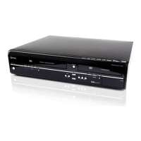
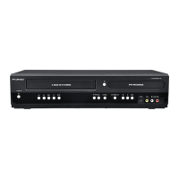
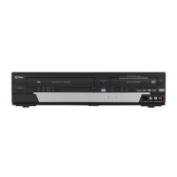
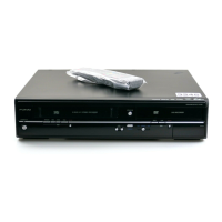
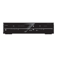
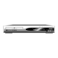
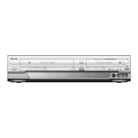
Details general technical specifications of the unit.
Lists specifications related to the Hard Disk Drive.
Outlines specifications for recording functions.
Details specifications for the TV tuner.
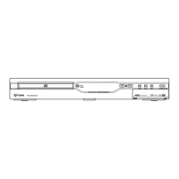
Lists and describes the unit's input and output terminals.
General safety notice regarding product components.
Specific safety guidelines for service personnel.
Verifying safe distance between components.
Testing for electrical current leakage.
Explains markings and pin indicators on circuit boards.
Procedures for connecting/disconnecting cables.
Requirement to use lead-free solder for repairs.
Instructions on how to access the unit's service mode.
Actions needed before proceeding with service.
Visual guide of disassembly steps.
Detailed instructions for removing parts.
Procedure to adjust head switching position.
Symbols indicating VCR operational status.
List of error codes and their meanings for the DVD section.
Troubleshooting steps for the power supply unit.
Troubleshooting steps specific to the HDD/DVD system.
Troubleshooting steps specific to the VCR system.
Diagram of the servo and system control functions.
Diagram of the subsystem control logic.
Diagram showing the digital signal processing flow.
Diagram of the video signal routing and selection.
Diagram of the audio signal routing and selection.
Diagram of the audio signal processing.
Diagram of the high-fidelity audio processing.
Diagram of the unit's power supply system.
Diagram of the secondary power supply circuits.
Diagram of the Digital TV module.
Important notes for interpreting schematic diagrams.
Detailed schematic for DVD/HDD Main CBA, part 1.
Detailed schematic for DVD/HDD Main CBA, part 2.
Detailed schematic for DVD/HDD Main CBA, part 3.
Detailed schematic for DVD/HDD Main CBA, part 4.
Detailed schematic for DVD/HDD Main CBA, part 5.
Detailed schematic for DVD/HDD Main CBA, part 6.
Detailed schematic for DVD/HDD Main CBA, part 7.
Circuit diagram for the DTV Module.
Circuit diagram for the SATA interface.
Top view illustration of the AV CBA layout.
Bottom view illustration of the AV CBA layout.
Top views for Power Supply, Function, SW, Rear Jack, USB, and Power SW CBAs.
Bottom views for Power Supply, Function, SW, Rear Jack, USB, and Power SW CBAs.
Specific pin details for IC501.
Specific pin details for IC612 (VFD Driver).
Guidelines for packing the unit for shipment or storage.
| Type | DVD Recorder |
|---|---|
| Video System | NTSC |
| Video Recording Format | MPEG2 |
| Audio Recording Format | Dolby Digital |
| Remote Control | Yes |
| Media Type | DVD-R, DVD-RW |
| Disc Compatibility | DVD-Video, DVD-R, DVD-RW, CD-DA |
| Tuner | NTSC |
| Output Resolution | 480i, 480p |
| Inputs | Composite, S-Video |
| Outputs | Composite video, S-Video |