Do you have a question about the FUNAI W4A-A4180DB and is the answer not in the manual?
Details on parts with special safety characteristics and potential hazards.
Specific safety measures to follow during repair.
Verifying spacing between components and chassis for safety.
Measuring electrical leakage to ensure safety compliance.
How to identify pins and connectors on circuit boards.
Guideline for using lead-free solder during repairs.
Procedures for desoldering and soldering surface-mount ICs.
Handling and connecting flexible foil connectors.
Proper grounding for personal safety against static discharge.
Setting up a grounded workspace to protect components.
Steps to access and operate the device's service mode.
Information about the optical sensor system.
Visual guide to the cabinet disassembly process.
Detailed steps for cabinet disassembly.
List of necessary tools for electrical adjustments.
Procedure to adjust head switching position during playback.
Steps to reset the DVD recorder to factory defaults.
Detailed steps for updating the device firmware.
Important warnings and notes regarding schematic diagrams and component replacement.
Guidelines for reading voltages, values, and component identification.
Warning on replacing fuses with the same type for fire safety.
Precautions for fixed/auto voltage power supply circuits.
Guidance on using part numbers and original replacement parts.
How to interpret voltage values in PLAY, REC, and DVD modes.
Method for understanding line connections in schematic diagrams.
Symbols and meanings for identifying test points on PCBs.
Component layout on the top side of the Sensor CBA.
Component layout on the top of the Power Switch CBA.
Component layout on the bottom of the Power Switch CBA.
Component layout on the top of the Function CBA.
Component layout on the bottom of the Function CBA.
Component layout on the top of the Front Jack CBA.
Component layout on the bottom of the Front Jack CBA.
Component layout on the top of the Rear Jack CBA.
Component layout on the bottom of the Rear Jack CBA.
Component layout on the top of the AFV CBA.
Component layout on the bottom of the AFV CBA.
Exploded view of the DVD mechanism and main circuit board.
Exploded view of the Sensor Circuit Board Assembly.
Exploded view of the Power Supply Circuit Board Assembly.
Exploded view of the Front Jack Circuit Board Assembly.
List of mechanical and electrical parts for DVD mechanism and main CBA.
Parts list for the MCV CBA.
List of parts for the Main CBA.
List of capacitors with their specifications and part numbers.
List of connectors with part numbers.
List of diodes with part numbers.
List of integrated circuits with part numbers.
List of coils with part numbers.
List of resistors with part numbers.
List of miscellaneous components with part numbers.
List of transistors with part numbers.
Continuation of the resistor list.
List of switches with part numbers.
Continuation of the connector list.
Continuation of the diode list.
Continuation of the IC list.
Continuation of the coil list.
Continuation of the capacitor list.
Continuation of the diode list.
Continuation of the IC list.
Continuation of the coil list.
Continuation of the resistor list.
Continuation of the miscellaneous parts list.
Continuation of the capacitor list.
Continuation of the diode list.
Continuation of the IC list.
Continuation of the coil list.
Continuation of the capacitor list.
Continuation of the diode list.
Continuation of the IC list.
Continuation of the coil list.
Continuation of the resistor list.
Continuation of the miscellaneous parts list.
| Brand | FUNAI |
|---|---|
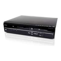
| Model | W4A-A4180DB |
| Category | DVD Recorder |
| Language | English |