1. MOUNTING
1-15
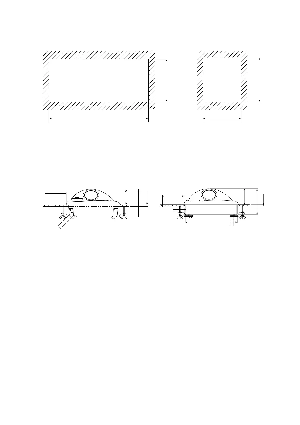
1. Prepare a cutout in the mounting location as shown in the figure below.
388 150
170±2 176
±2
±2
±2
For RCU-014 For RCU-015 and RCU-016
2. Set the control unit to the cutout.
3. Attach the mounting plate to the control unit with four screws from the rear side.
4. Screw the wing screw to each mounting plate and then insert hex bolt to each wing
screw.
5. Fasten each wing screws and then fasten the hex nuts as shown in the figure below.
(P)
#70
53
92
(P)
#70
171
53
86
Note: P 10
<
=
RCU-014 RCU-015/RCU-016


 To Next Page