Do you have a question about the Furuno FEA-2107-BB and is the answer not in the manual?
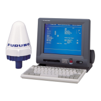
Details the components of the ECDIS EC1000C Workstation and its connections to navigation sensors.
Describes voyage planning as the preparation phase, including route definition, calculation, and optimization.
Explains positioning using navigation sensors and Kalman filter technology for accurate position calculation.
Details the types of electronic charts used (S57 ENC, CM-93, ARCS) and information displayed.
Explains operator control using the RCU-018 or RCU-015, including trackball, mouse buttons, and scrollwheel.
Instructions to update ARCS and S57 chart material before a new voyage.
Details the process of creating a new route or modifying an existing one for voyage planning.
Guides on selecting and preparing a route for monitoring, including route selection and checking conditions.
Explains how to choose navigation sensors and view their current values for accurate navigation.
Details S57 charts, their compatibility with official IHO standards (ENC), and update types (incremental, reissues).
Provides a flowchart and procedure for loading S57 charts into the ECDIS, including SENC conversion.
Explains SENC conversion, including speeding up the process and handling failed conversions.
Describes RENC services, permits, product lists, and authentication required for ENC chart usage.
Explains how to choose vector chart material, display charts, control features, and use display bases.
Describes ARCS charts as digital reproductions of BA paper charts, covering their availability and updates.
Covers ARCS subscription services (Navigator, Skipper), license information, and starting with ARCS charts.
Explains how to display ARCS charts, choose chart datum, view different charts, and control visible features.
Provides instructions for using the manual update editor to plan, insert, delete, and modify chart objects.
Explains how to use the manual update editor with true symbols for creating, modifying, or deleting chart objects.
Explains how ECDIS detects dangerous areas and generates alarms for safety contour or specified condition violations.
Outlines the procedure for setting chart alarms, including choosing safety contour and objects for alarm calculation.
Details how to use Danger Symbol, Danger Line, and Danger Area from user charts for chart alarm calculation.
Explains how to set the watch sector for ship's predicted movement area and activate Own Ship Check.
Details navigation marks like Reference Point, EBL, VRM, Parallel Index, and Range Rings.
Defines a route plan and its components, including waypoints, channel limits, and navigation methods.
Provides a step-by-step guide to creating a new route, including naming, waypoints, and alarms.
Details how to modify an existing route, including parameters, waypoint positions, and data.
Explains route optimization strategies like Max Speed, Time Table, Max Profit, and Min Cost.
Defines route monitor as a means for permanent monitoring of ship's behavior relative to the monitored route.
Guides on how to select a route to monitor from the status bar and Monitor combo box.
Explains how the system highlights chart alarms inside channel limits and predicted movement areas.
Lists and explains alarms related to route monitoring, including permanent and intermittent types.
Defines user charts as simple overlay charts for operator purposes, for highlighting safety items and activating alarms.
Guides on activating monitoring mode and choosing a user chart, indicated by color in the status bar.
Explains how to activate planning mode and choose a user chart, indicated by color in the status bar.
Provides a step-by-step guide to creating user charts, including points, symbols, lines, areas, and tidals.
Guides on adding new user chart objects using the left mouse button or the Add button.
Guides on preparing pilot data, switching between plan and monitor modes, and creating new pilot data.
Explains how to activate monitoring mode and choose pilot data, indicated by color in the status bar.
Explains how to activate planning mode and choose pilot data, indicated by color in the status bar.
Provides step-by-step instructions for creating new pilot data records and modifying existing ones.
Guides on backing up chart material to a backup ECDIS to keep the database identical.
Explains how to restore chart material from a backup ECDIS to the ECDIS hard disk.
Explains how to control the common reference system by setting workstation mode, usage rights, and sensor source.
Explains how to select a workstation as the sensor source for all navigation sensors.
Provides troubleshooting steps for common issues like pending access server windows and harmonization failures.
Explains how to choose navigation sensors and view their current values via the Sensors dialog box.
Details how the system chooses position sources (primary, secondary, Kalman filter) and associated indications.
Illustrates how various navigation data sources are chosen for SOG, COG, speed, heading, ROT, and drift.
Explains the automatic multi-sensor Kalman filter for position estimation and sensor reliability monitoring.
Covers the position alignment feature for fine-tuning ship's position using radar overlay and chart details.
Explains how ARPA-tracked targets can be displayed on the ECDIS display by selecting Std or Oth.
Details how to view ARPA target data, including basic and detailed information, and setting CPA/TCPA limits.
Introduces AIS transponder connectivity to ECDIS for displaying AIS targets and managing storage.
Details how to display AIS targets on ECDIS, including setting max number, range, and filtering.
Explains how to view AIS target data, including basic and detailed information, and setting CPA/TCPA limits.
Explains how to send and receive AIS safety messages for warning of navigation hazards.
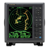
Introduces radar overlay, allowing radar echo images on ECDIS chart display via LAN or overlay card.
Provides steps to activate radar overlay on ECDIS, choosing display modes like 'ECDIS only' or 'ECDIS and radar'.
Explains how to select the radar video source for overlay, either through LAN or radar overlay card.
Details controls for adjusting radar image parameters like gain, sea clutter, rain clutter, and video processing.
Covers error sources for radar echo and chart display mismatch, and radar echo/ARPA target mismatch.
Introduces ECDIS recording functions for voyage-related items like ship movement, position, and radar targets.
Details the types of voyage data recorded, including details log, voyage log, danger targets log, chart usage log, and alarms log.
Details the danger target log, storing information about ARPA and AIS targets within CPA and TCPA limits.
States ECDIS uses WGS-84 datum for ENC material and requires positioning devices to work in WGS-84.
Introduces Initial Settings menu containing installation, navigation, and optimization parameters.
Details basic ship parameters for steering and navigation, crucial for integrated navigation system function.
Explains how optimization parameters are used for calculation, defining ship's fuel consumption at different speeds.
Covers color calibration settings, including color tests for ARCS and S57 charts, and gray scale test.
Details how the ECDIS receives sensor data and displays results on the conning display (option).
Lists the steering modes available: Hand Steering, Autopilot Steering, Waypoint mode, and Track mode.
Describes the Autopilot FAP-2000 control panel, detailing its various buttons and indicators.
Details automatic route steering modes: Go to Waypoint and Go to Track, activated within monitored route channels.
Provides summaries of system behavior during critical failures like lost heading, speed, or communication.
Lists available steering modes: Hand steering, Autopilot steering, and Track mode automatic Route steering.
Details automatic route steering, its characteristics, preconditions, and activation procedures.
Summarizes system behavior during critical failures like lost heading, speed, or communication for NAVI mode.
Lists available steering modes: Hand, Autopilot, NFU, Track mode automatic Route steering, and Remote Control.
Details automatic route steering modes: Open Sea (Goto OS) and All Waters (Goto AW).
Provides summaries of system behavior during critical failures like lost heading, speed, or communication.
Provides comprehensive lists of navigation alarms, chart alarms, steering alarms, and radar overlay related alarms.
Offers a troubleshooting table for common faults and remedies to restore normal operation.
Maintains chart database for both vector (S57) and Raster charts (ARCS).
Mainly controls visibility of chart related objects, allowing customization of displayed chart features.
Explains how to set up various sensors connected to the ECDIS and view their status.
| Power Output | 25 kW |
|---|---|
| Range Scales | 0.125 to 96 NM |
| AIS | Yes |
| Range | Up to 96 NM |
| Rotation Speed | 24 RPM |
| Power Supply | 12/24 V DC |
| Target Tracking | 100 targets |
| Frequency | 9410 MHz |
| Beam Width | 1.9° horizontal |
| Antenna Length | 6 feet (1.8 meters) |