viii
SYSTEM CONFIGURATION
Basic configuration is shown with solid line.
Environmental category
All units (other than VR-7021F/7024F, VR-7022F, VR-
7012W and VR-7020)
Protected from the weather
VR-7021F/7024F Portable
VR-7022F, VR-7012W, VR-7020 Exposed to the weather
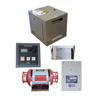
Data
Collecting
Unit (DCU)
VR-7010
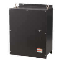
Fixed Data Recording Unit (Fixed DRU)
VR-7020*
3
Float-free Data Recording Unit
(Float-free DRU)
VR-7021F/7024F*
3
Video LAN Converter
IF-7100
24 VDC
PC
Live Player V5
VR-7030
100-230 VAC
Remote Alarm Panel
VR-7017*
1
Microphone
VR-7011
Waterproof Microphone
VR-7012W
Max. 8 units
Radar/ECDIS display
100-230 VAC
100-230 VAC
Max. 2 units
Radar, ECDIS, etc.
VHF Audio
- Serial Interface: Max. 2 ch
(IEC 61162-1/2)
- Serial Interface: Max. 6 ch
(IEC 61162-1)
Intelligent HUB
HUB-3000
*4
Sensor Adapter
MC-3000S
Sensor Adapter
MC-3010A
Sensor Adapter
MC-3020D
Serial Interface
Analog Interface
Digital IN Interface
Junction Box
VR-7022F*
3
Network
Equipment
Power Supply Unit
PSU-011*
2
Junction Box
IF-8540
or
IF Signal
*
1
: Nominal viewing distance: 0.5 m
*
2
: For Russian vessel only.
*
3
: When using the VR-7000S, select either the
“VR-7020” or the “VR-7021F/7024F and
VR-7022F”.
*
4
: Use Switching HUB (HUB-100) for
IEC61162-450 Ed.1 compliant network.
Max. 2 units
Intelligent HUB
HUB-3000
*4
 Loading...