49
<Receiver and Servo Installation>
MODEL BASIC SETTING PROCEDURE
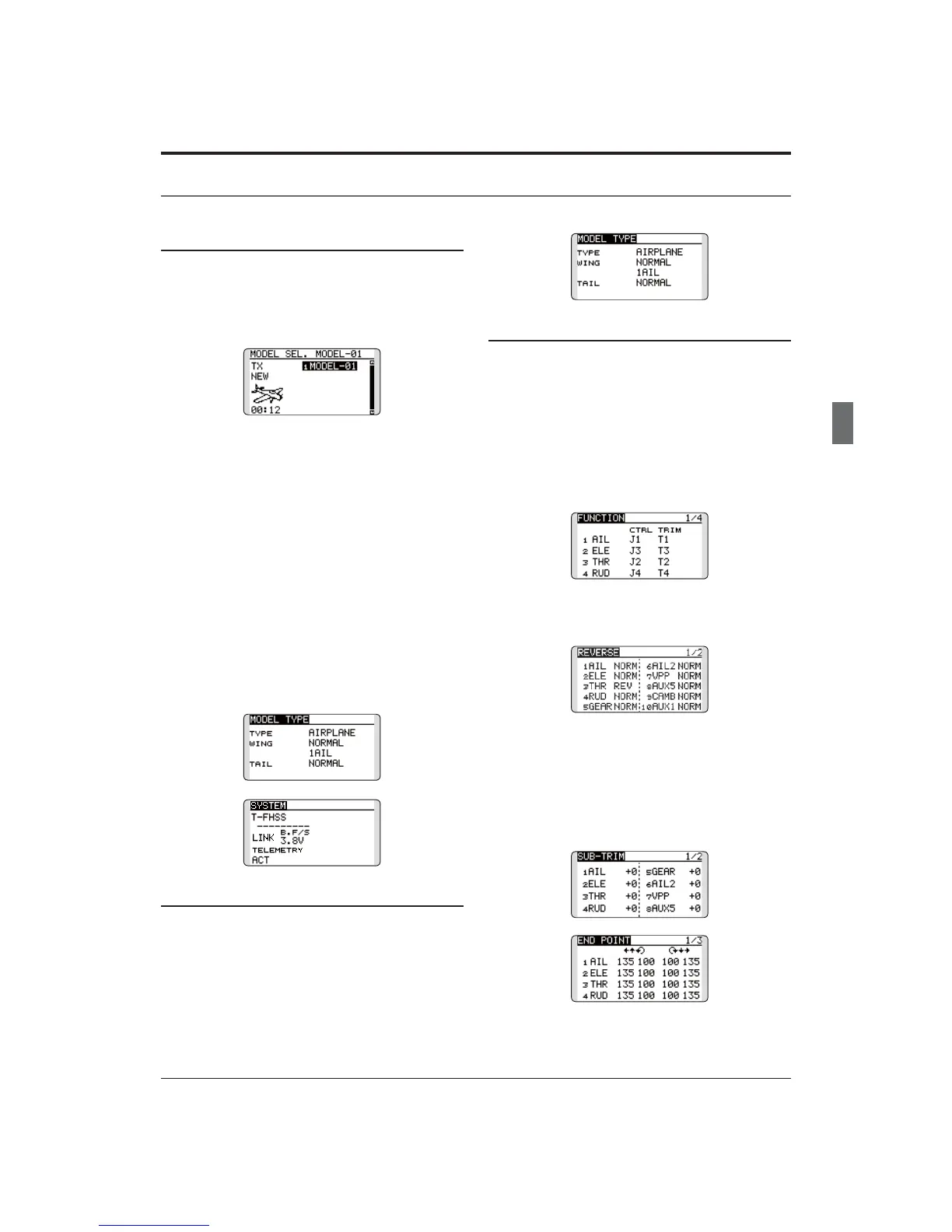
1. Model addition and selection
Initially, the T12K assigns the first model to
PRGHOLQWKHWUDQVPLWWHU7KH0RGHO6HOHFW
function of the Linkage Menu is used to add
models and to select amongst models which are
already set.
7KH7.LVFDSDEOHRIVWRULQJGDWDIRUXSWR
models in its internal memory. Additional model
GDWDFDQDOVREHVDYHGWRDQRSWLRQDOPLFUR6'
card.
The currently selected model name is displayed
LQWKHFHQWHURIWKHKRPHVFUHHQ%HIRUHÀ\LQJDQG
before changing any settings, always confirm the
model name.
When a new model is added, the Model type
VHOHFWVFUHHQDQG6\VWHPPRGHVHWXSVFUHHQ
automatically appear. Please be aware that the
transmitter will stop transmitting temporarily when
you change the model.
:KHQDQHZPRGHOLVDGGHG\RXZLOOQHHGWRUH
link the receiver.
2. Model type selection
6HOHFWWKHPRGHOW\SHPDWFKHGWRWKHDLUFUDIW
with the Model Type select function of the Linkage
Menu. For an airplane, select the model type from
among the 2 types: airplane and glider. And then
select the wing type and the tail type matched to
the aircraft.
Airplane/glider basic setting procedure
3. Fuselage linkage
Connect the ailerons, elevators, throttle, rudder,
HWFLQDFFRUGDQFHZLWKWKHPRGHOVLQVWUXFWLRQ
manual. For a description of the connection
PHWKRGVHHWKH5HFHLYHUDQG6HUYRV&RQQHFWLRQ
Note that even for the same "airplane
model", when the wing type and tail type
are different, the channel assignment may
be different. (The channel assigned to each
function can be checked at the Function
menu of the Linkage Menu.)
ŏ ,IWKHGLUHFWLRQRIWKHVHUYRLVLQFRUUHFWDGMXVW
WKHGLUHFWLRQZLWKWKH5HYHUVHIXQFWLRQRIWKH
/LQNDJH0HQX
ŏ $GMXVWWKHQHXWUDOSRVLWLRQDQGFRQWURO
VXUIDFHDQJOHZLWKWKHOLQNDJHDQGILQH
WXQHWKHPZLWKWKH6XE7ULPDQG(QG3RLQW
IXQFWLRQVDQJOHDGMXVWPHQW7RSURWHFWWKH
OLQNDJHDOLPLWSRVLWLRQFDQDOVREHVHWZLWK
WKH(QG3RLQWIXQFWLRQ7KH(QG3RLQWIXQFWLRQ
FDQDGMXVWWKHDPRXQWRIXSGRZQDQGOHIW
ULJKWPRYHPHQWDQGOLPLWRIHDFKFKDQQHO