ATL display
Steering D/R display
Steering trim display
Throttle trim display
DT2
DT1
DT3
DT4
DT5
Mechanical ATL
adjusting screw
21
Before Using
Steering And Throttle Trim Operation
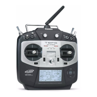
Digital Trim Operation
(Initial settings: DT1: Steering trim, DT2: Throttle trim, DT3: Channel 3, DT4: Steering D/R, DT5: ATL-Brake rate)
2SHUDWLQJE\WKHWULP3XVKWKHWULPOHYHUWRWKHOHIWRUULJKWXSRUGRZQ7KHFXUUHQW
SRVLWLRQLVGLVSOD\HGRQWKH/&'VFUHHQ
• Each step is indicated by a tone.
• When the trim exceeds the maximum trim adjustment range, the
beep will change and the servo will not move any farther.
• Steering D/R: The steering left and right servo travels are ad-
justed simultaneously.
• ATL: Decreases the set value when the braking effect is strong
and increases the set value when the braking effect is weak.
:LWKWKHFHQWHUWULPIHDWXUHWULPDGMXVWPHQWVKDYHQR
effect on the maximum servo travel. This prevents the
OLQNDJHVIURPELQGLQJZKHQDGMXVWPHQWVDUHPDGH
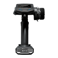
Adjustment
1
Using a 1.5 mm hex wrench, adjust the trigger
brake (reverse) stroke. (The screw moves the
throttle trigger stopper.)
:KHQWKHVFUHZLVWXUQHGFORFNZLVHWKHVWURNHEHFRPHVQDUURZ
HU$GMXVWWKHVWURNHZKLOHZDWFKLQJWKHVFUHZ
Note:
Mechanical ATL Adjustment
0DNHWKLVDGMXVWPHQWZKHQ\RXZDQWWRGHFUHDVHWKHVWURNHRIWKHEUDNHEDFNVLGHRI
the throttle trigger to your preferences.
2QFH\RXKDYHFKDQJHGWKHPHFKDQLFDOVWURNHRQWKHEUDNHVLGHEHVXUHWRDGMXVWWKH
scale of the throttle channel accordingly by using the
"
$GMXVWHU
"
IXQFWLRQSDJH
'XHWRWKLVFKDQJH\RXDOVRQHHGWRDGMXVWLQPRVWFDVHV WKHWUDYHORIWKHWKURWWOH
servo by using
"
(QG3RLQW$GMXVWHU
"
.