The flow charts show a complete listing of parameters. For the
actual application the number of available parameters is
dependent on the setup conditions, and should be less than that
shown in the flow charts.
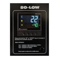
Press key for 4 seconds to enable up/down key function, and
the LOCK indicator led will be extinguished.
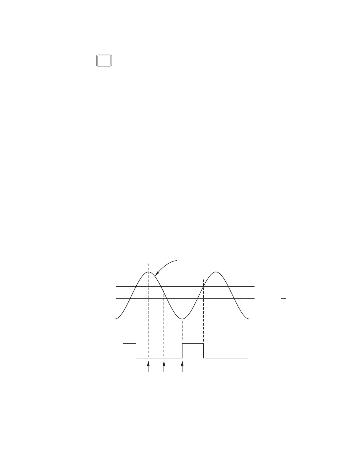
If Hi. is selected for OUT1, the unit will perform high limit control. When power
is applied the OUT1 relay is de-energized. After 6.5 seconds self-test period,
if the process is below the high limit set point (HSP1), the output 1 relay will
be energized and OP1 indicator will go off. If the process goes above the
high limit set point, the relay will be de-energized, the OP1 indicator will go
on and the display will show the process value. After the process falls below
the high limit set point and the RESET key is pressed or the remote reset input
is applied, the relay will be energized and the OP1 indicator will go off.
NOTE: Hysteresis is safe-sided.
RESET
Note 1.Note 1.
Note 2.Note 2.
1-6 Limit Control Operation1-6 Limit Control Operation
HIGH LIMIT OPERATIONHIGH LIMIT OPERATION
HSP1
ON
OFF
OUT1 Relay
A, B ,C=Reset is applied
O1.HY= Output1 hysteresis
Figure 1-4 High Limit OperationFigure 1-4 High Limit Operation
PV
AB
C
13
HSP1 O1.HY
UM L91-Rev 8