Chapter 3 ProgrammingChapter 3 Programming
3-1 Process Input3-1 Process Input
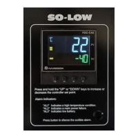
Press for 4 seconds to enter setup mode. Press to select the
parameter. The display will indicate the parameter symbol and the value
( or selection ) for that parameter.
INPT: Selects the sensor type and signal type for the process input.INPT:
UNIT: Selects the process unit.UNIT:
RESO: Selects the location of the decimal point (Resolution) for
most (not all) process related parameters.
RESO:
IN.LO: Selects the low scale value for the Linear type inputIN.LO:
IN.HI: Selects the high scale value for the Linear type inputIN.HI:
Hidden if: T/C or RTD type is selected for INPTHidden if:
Hidden if: T/C or RTD type is selected for INPTHidden if:
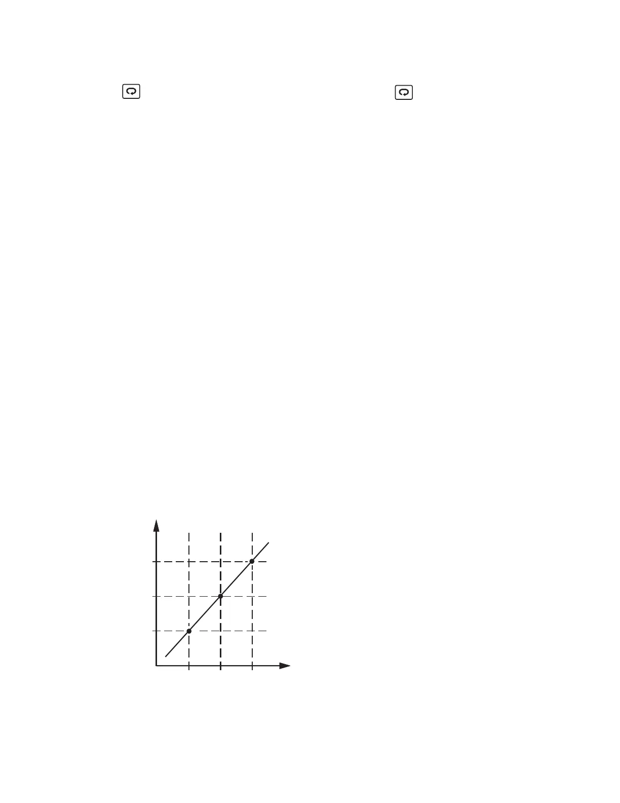
How to use IN.LO and IN.HI:How to use IN.LO and IN.HI:
If 4-20mA is selected for INPT, let SL specifies the input signal low (ie.
4mA), SH specifies the signal high (ie. 20mA), S specifies the current
input signal value, the conversion curve of the process value is
shown as follows:
IN.LO
process value
PV
IN.HI
SL SHS
input signal
Figure 3-1 Conversion Curve for
Linear Type Process Value
Figure 3-1 Conversion Curve for
Linear
Type Process Value
33
UM L91-Rev 8