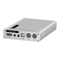
Computer module »U2-R-CPU«
94 · Computer and console modules
Installation
Connecting the computer
RS232: Use the RS232 cable to connect the computer’s 9-pin serial computer inter-
face to this interface (optional).
Trans.: Use a category 5e (or better) twisted pair cable to connect this interface to the
Dynamic
Port of the USB/RS232 Main Channel that is assigned to the computer.
USB CPU: Use the USB device cable to connect one of the computer’s USB ports to this
port.
Power In: Insert the connection cable of the power pack to this interface. Now con-
nect the power cable to the power pack and a power outlet.
Status displays
The blinking Transmission LEDs show the following connection statuses:
LED Status Meaning
Yellow Off No connection to network.
On A console module is accessing the computer module.
Green On A console module is accessing the computer module.
Blinking No communication with the counterpart.
Flashing Connection to the counterpart established successfully.
No console module is accessing.