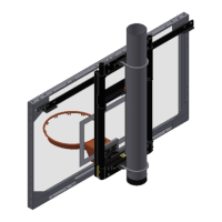
2500 Wall Mount
11
WOOD PAD INSTALLATION
Instructions for 2 500 Side Folding Wall Mounts
1) Wood pads are provided for use in anchoring the units to the walls.
2) Verify all dimensions and locations with the General Contractor using the latest
architectural prints before beginning. Also, verify floor thickness if not working over a
finished floor. NOTE: All production drawing dimensions override any dimensions
contained within this manual.
3) Mark the centerline of the unit on the wall utilizing the best method available.
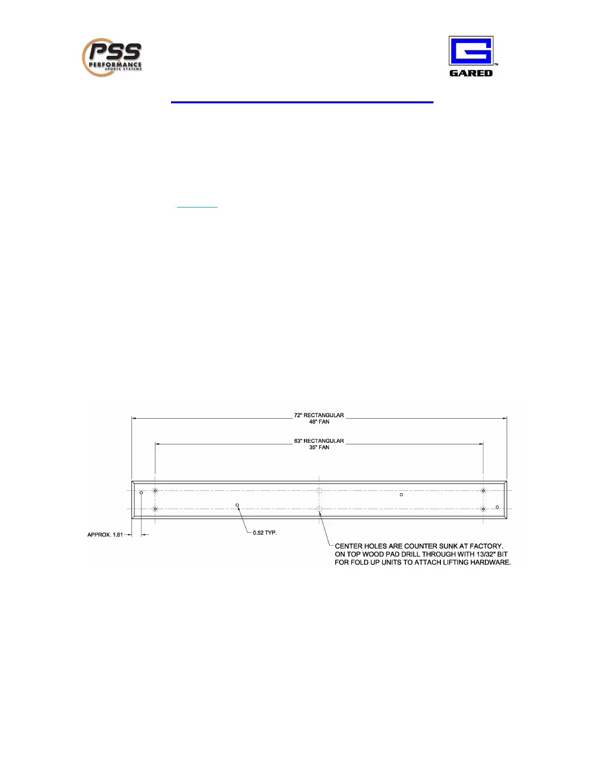
4) Mark the centerline of the wood pad. Wood pads for rectangular boards are 72” w ide,
with predrilled bracket locations spaced 63” center to center. Wood pads for fan shaped
boards are 48” wide, with predrilled bracket locations spaced 35” center to center.
Anchors should be spaced to allow installation of chain and structure bracket s without
interference. The recommended layout is to have one anchor on each end of the wood
pad (center approximately 1 13/16” from the outer most edge of the wood pad) and two
evenly spaced in the center of the wood pad (see figure 1).
5) Next mark anchor locations on the wood pad and drill through.
6) Use the holes drilled in the wood pad as a template to mark the anchor holes on the wall.
Mark and drill the anchor holes in the wall. PSS recommends pads be bolted through the
wall with through bolts and an chor plates. When it is not possible to bolt through the
wall contact the structural engineer for the building for advice.
Figure 1. Generic w ood pad drawing with recommended anchor locations.
NOTE: Anchor holes should not be dri lled in line with each other or existing bracket holes.
7) Attach the brackets to the wood pad. Brackets for the chains should be spaced the same
as the pipe supports. NOTE: Attach the quick links and chains to the brackets prior
to anchoring the wood pads to the wall.
8) After all brackets are in place, anchor the wood pads in place on the wall, making sure to
place the wood pads for chains and supports in the correct locations (per F igure 2 ).