

M
Margaret FosterSep 10, 2025
What does it mean if Garmin Transceiver RAM failed?
- JJoshua OrtegaSep 12, 2025
If your Garmin Transceiver RAM failed, replace the CPU Board.

What does it mean if Garmin Transceiver RAM failed?
If your Garmin Transceiver RAM failed, replace the CPU Board.
| Display Type | LCD |
|---|---|
| Power Supply | 10-32 VDC |
| Frequency Range | 118.000 to 136.975 MHz |
| Channel Spacing | 25 kHz |
| GPS | Yes |
| Type | GPS/COM |
| Navigational Capabilities | GPS |
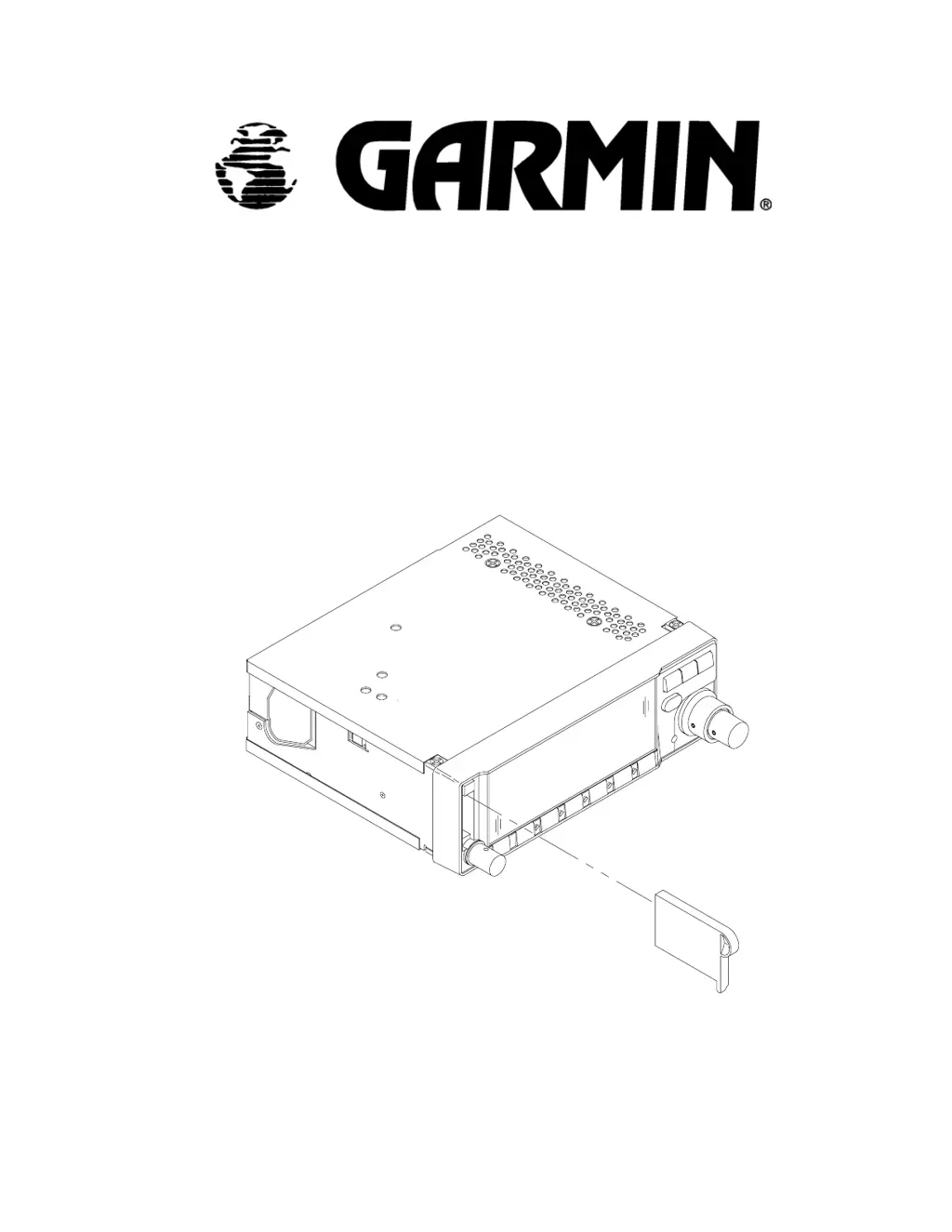
Details on the physical and operational aspects of the units.
Description of various input/output connectors and their functions.
Information regarding FCC compliance and licensing for the units.
Guidelines for selecting locations and mounting antennas for optimal performance.
Recommendations for GPS antenna placement on the aircraft.
Guidelines for locating the COMM antenna to avoid interference.
Requirements for electrical bonding between antennas and aircraft structure.
Limitations for GARMIN's GA 56 antennas and COMM antenna.
Strategies to prevent VHF COMM interference with GPS reception.
Instructions for installing the COMM antenna as per manufacturer's recommendations.
Factors to consider when installing the unit rack in the aircraft panel.
Ensuring pilot access and visibility of the unit in the rack.
Recommendations for antenna cable types, lengths, and routing.
Importance and method of providing cooling air to the unit.
Requirement for annunciators when interfacing with other flight instruments.
Optional pressure altitude input for system performance enhancement.
List of available antenna and rack installation accessories.
Step-by-step guide for installing the GPS antenna.
Instructions for routing and installing coaxial cables and connectors.
Procedure for installing the unit's rack into the aircraft instrument panel.
Method for installing and removing the unit from its rack.
Checking COMM antenna installation for insertion loss and VSWR.
Requirement for installing a VFR use placard.
Procedures for entering and operating the unit's test modes.
Steps for configuring unit settings after installation.
Adjusting display intensity, backlight, and brightness settings.
Configuring input and output for I/O Channel 1.
Configuring output for ARINC 429 communication.
Procedure for calibrating the Course Deviation Indicator (CDI).
Setting up aircraft-specific configurations like fuel type and remote battery.
Configuring input and output for I/O Channel 2.
Procedures for performing ground tests on various unit functions.
Testing the status of external power, battery, and memory.
Verifying CDI and flag indications during test mode.
Testing the functionality of message and arrival annunciators.
Testing remote switches for COMM functions.
Performing loopback tests for RS232 and ARINC 429 channels.
Verifying altitude input readings in test mode.
Testing the OBI data and values for validity.
Testing for successful GPS signal acquisition and data display.
Optional procedure to evaluate VHF COMM interference.
Performing a flight test to verify VHF COMM transceiver performance.