190-01182-02 GTR 225/GNC 255 TSO Installation Manual
Rev. F Page 5-14
5.2.10 DME Tuning
5.2.10.1 DME Tuning Function
The GTR/GNC can channel a DME based on the tuned VOR/LOC frequency. The GTR/GNC 2 of 5,
BCD, or Slip parallel DME and King Serial DME channeling format. When DME COMMON is held low,
the GTR/GNC actively tunes the DME.
5.2.10.2 DME Tuning Electrical Characteristics
5.2.10.2.1 Parallel DME Tuning
For each of the parallel DME tuning discrete outputs, the driver output voltage is not more than 1.0 V
while sinking 20 mA. The maximum off state leakage current with respect to ground is less than 10 A.
DME COMMON must be pulled low to indicate to the GTR/GNC that it is the device channeling the
DME.
DME COMMON is considered active if either the voltage to ground is less than 1.9 V or the resistance to
ground is less than 375 . These inputs are considered inactive if the voltage to ground is 11-33 VDC.
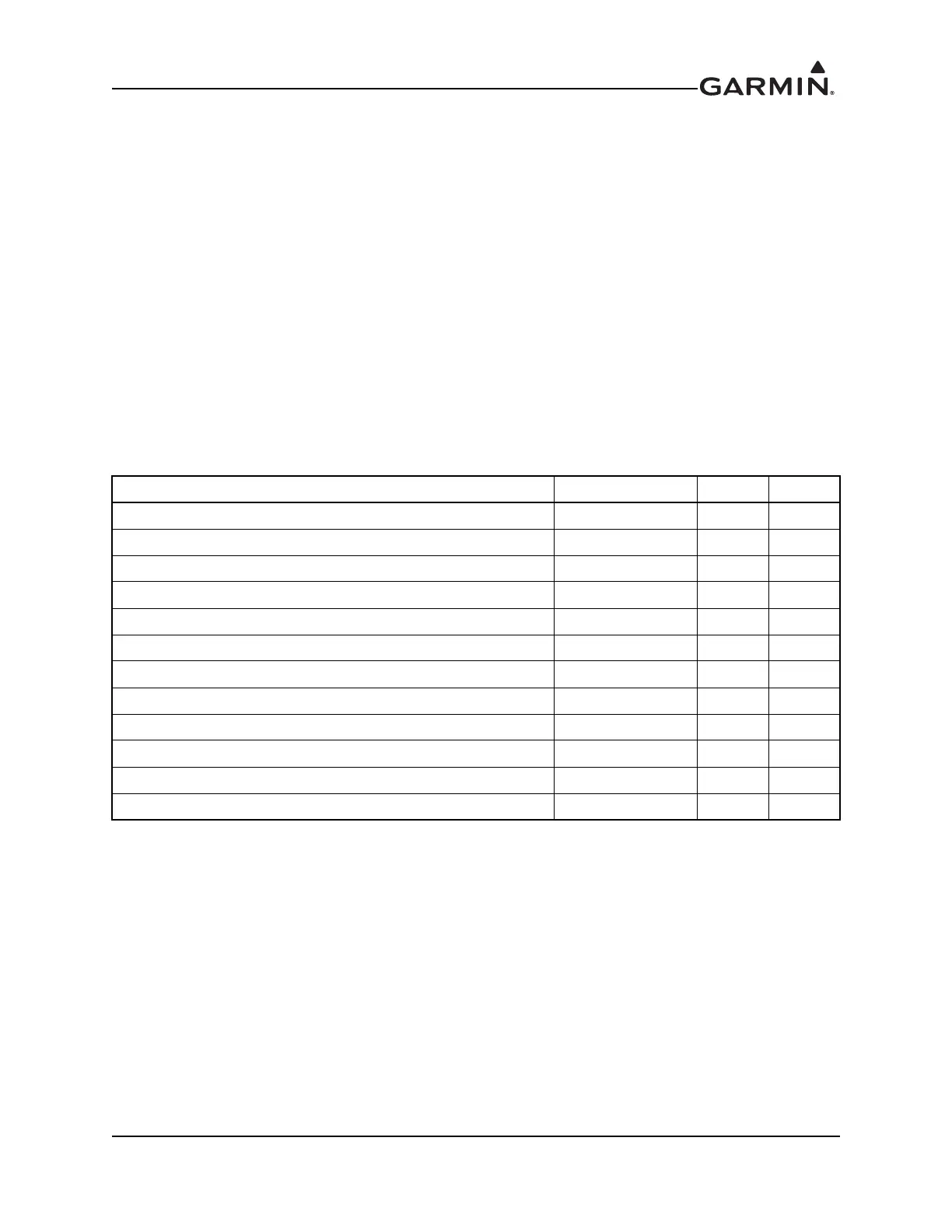
Pins 37, 40, 41, 42, 43, 45, 47, 33, 54, and 56 are configured for 2 of 5 parallel DME tuning.
Pin Name Connector Pin I/O
PAR DME 100kHz-A/SERIAL DME ON P2002 37 Out
PAR DME 100kHz-B P2002 39 Out
PAR DME 100kHz-C P2002 40 Out
PAR DME 100kHz-D P2002 42 Out
PAR DME 100kHz-E P2002 54 Out
PAR DME 50kHz P2002 43 Out
PAR DME 1MHZ-A P2002 45 Out
PAR DME 1MHZ-B P2002 46 Out
PAR DME 1MHZ-C P2002 47 Out
PAR DME 1MHZ-D/SERIAL DME ON P2002 33 Out
PAR DME 1MHZ-E P2002 56 Out
DME COMMON P2002 41 In
 Loading...