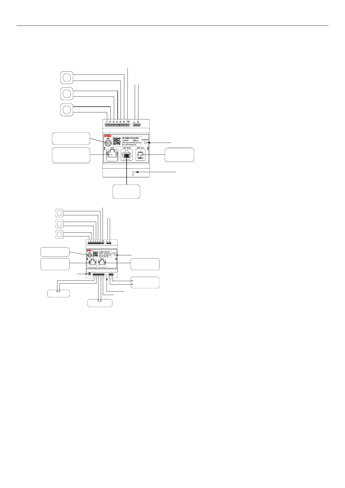
4.14.2 DYNAMIC LOAD MANAGEMENT (DLM) INSTALLATION OVERVIEW
CT1
CT2
CT3
PE/GND
L N
Indication light
HAN(RJ12)
Utillity Energy
meter
CT1-3: 0-333 mV output
HAN (RJ45)
Utillity Energy
meter
Ethernet
Connect to charging station,
other load interface
or network switch.
Wi-Fi antenna
FUNCTIONAL
BUTTON
GARO Entity Balance Basic
CT2-/GND(Black) L
CT1-/GND (Black) L
CT2+ (White) K
CT1+ (White) K
CT3-/GND(Black) L
CT3+ (White) K
PE/GND
L N
M-Bus Energy Meter
M-Bus +
M-Bus -
Modbus Energy Meter
+ -
+ B- A
Modbus B/Z +
Modbus A/Y -
GND
Relay controlled
auxillary unit
max 250V AC, 30V DC
max, 10A
+
IN
Wi-Fi antenna
Ethernet
Connect to charging station,
other load interface
or network switch.
Modbus termination
Indication light
CT1
CT2
CT3
Ethernet
Connect to charging station,
other load interface
or network switch.
CT1-3: 0-5 A output
FUNCTIONAL
BUTTON
GARO Entity Balance Advanced
CT2-
CT1-
CT2+
CT1+
CT3-
CT3+
65
Installation