3
Remove crimper, back-up ring, no notched die cone
(notched die cone sold separately PN 7482-0297),
die magnet, hose assembly, mounting bracket with
bolt, jar of Molykote “G” grease, operating manual,
crimp data book and crimp decals from shipping
carton. Locate serial number on base plate in front
of left post and record on Page 1. Be sure to fill out
the crimper registration card. (By completing the
card and returning it to Gates, you will receive crimp
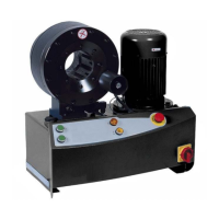
data updates and full warranty coverage.) Remove
pump, breather cap and operating manual from its
shipping carton.
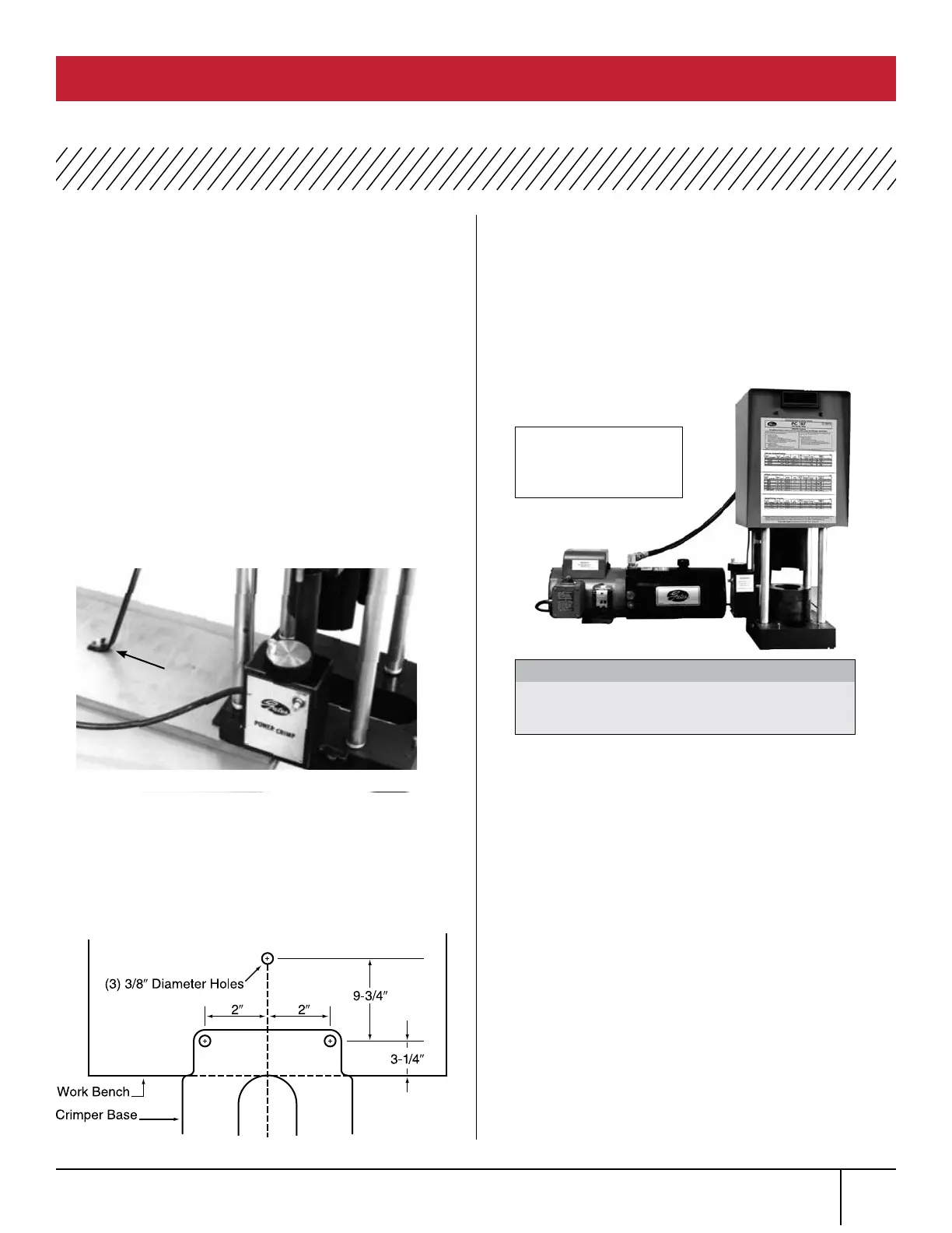
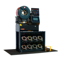
Mount crimper so it overhangs a workbench (as
shown in Photo 1). The back of the cutout (in the
base plate) should be in line with front of bench.
The bench should be 37” to 42” high, stable and of
sturdy construction.
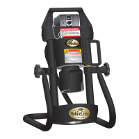
Drill three 3/8” diameter holes as shown in
Illustration 1. Connect the mounting bracket to top
rear of crimper and to the hole farthest from edge
of workbench. Further secure crimper to workbench
using the two remaining holes.
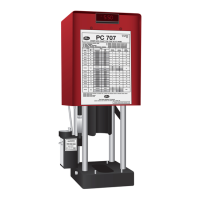
When crimper is secured to the workbench, connect
hose assembly between crimper and pump.
Connect receptacle on short cord of pump to plug
on cord of switch box of the crimper. If plug and
receptacle do not match, do not try to connect.
Differences in the plug and receptacle indicate
the pump and crimper have different voltages and
should not be operated.
Remove plug from top of pump reservoir and replace
with breather cap provided. Check that hydraulic oil
is within 1/2” of bottom of plug opening. If needed,
add Dextron II ATF or equivalent to reservoir.
Verify that switch on pump electrical box is in “OFF”
position. Connect pump power cord to a 15 amp
(minimum) rated electrical circuit.
Move switch on pump electrical box to “ON” position.
This will provide power to the pump and crimper.
Turn knob on top of crimper switch box to get a
setting of 2.00 on the readout. Cycle crimper at
least 5 times to bleed air from cylinder and
hydraulic system.
Peel and position crimp
decal on the shroud
according to your
preference.
Crimper and pump voltage must be the same
or digital readout will be damaged.
WARNING:
ILLUSTRATION 1
PHOTO 1
Mounting
Bracket
SETUP
PC 707 CRIMPER SAFETY AND OPERATING MANUAL
1.
2.
3.
4.
5.
6.
7.
8.
9.