4
Before initiating calibration procedure, make sure
crimper has been cycled five times. To cycle, dial in
a setting of 2.00 and run crimper down to shutoff
with no die set loaded.
Install the “733” die set to calibrate the machine
using an 8G MegaCrimp
®
coupling.
Set the digital readout setting to 5.20. (Rotating the
knob on top of switch box clockwise will increase the
number; counterclockwise will decrease the number.
When changing the setting, always move to a higher
number then down to the desired setting. Example:
To change from 5.00 to 5.20, move dial up to 6.00
then down to 5.20.) The readout figures may jump a
number; i.e. 5.20 to 5.19 or 5.21. This will not affect
the crimp OD.
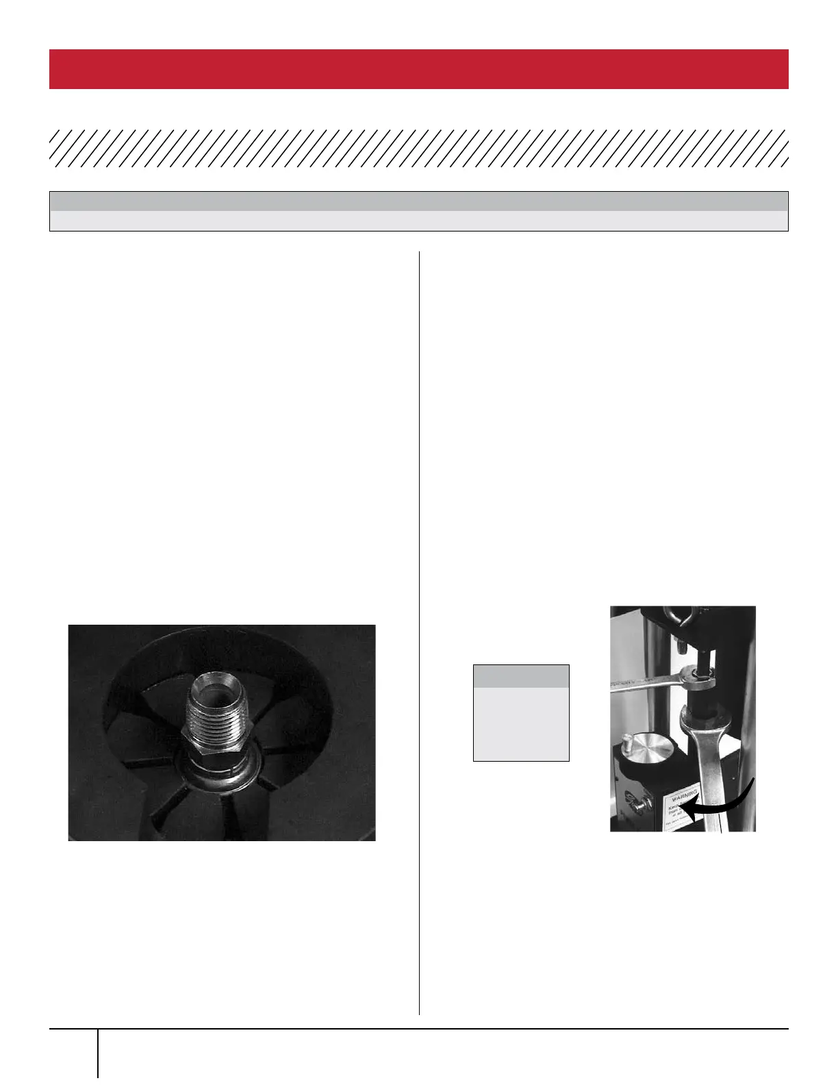
Insert the coupling into the die set approximately
1/8” below top of die. (See Photo 1.)
Slide the die cone assembly under the ram until it
stops against back locating pins and push the crimp
button and hold. Release the button immediately
when the pump stops.
Remover coupling and measure crimp diameter, which
should measure 1.000” ± .003”.
(See Page 9 for Measuring Crimp Diameter.)
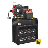
If ferrule crimp diameter is not acceptable, adjust
actuator rod. (See Photo 2.)
a. To increase crimp diameter – Hold the
1-1/16” actuator rod while loosening the 3/4”
lock nut. Rotate the actuator rod clockwise (one
full turn of the actuator rod will change crimp
diameter approximately 0.024”). Then tighten the
lock nut down.
b. To decrease crimp diameter – Hold the
1-1/16” actuator rod while loosening the
3/4” lock nut. Rotate the actuator rod counter
clockwise (one full turn of the actuator rod will
change crimp diameter approximately 0.024”).
Then tighten the lock nut down.
Repeat steps 3 through 7 to verify correct
crimp diameter.
Make sure area under pusher cup is clear of die cone or die sets.
WARNING:
PHOTO 1 (SHOWN WITH OPTIONAL NOTCHED DIE CONE)
PHOTO 2
CLOCKWISE
Do not
over-tighten
lock nut.
CAUTION:
PC 707 CALIBRATION PROCEDURE
PC 707 CRIMPER SAFETY AND OPERATING MANUAL
1.
2.
3.
6.
7.
8.
4.
5.