9
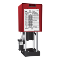
SKETCH 2
DO NOT measure on top of
part number stamps.
NOTE:
TO PROPERLY MEASURE A CRIMP DIAMETER:
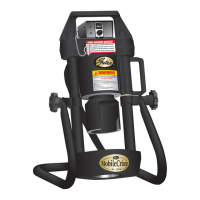
FIG. 1
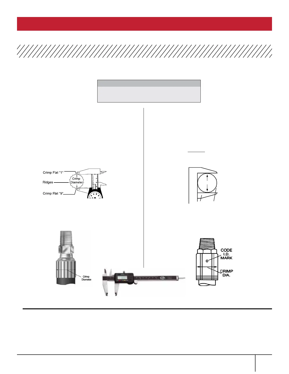
SKETCH 1
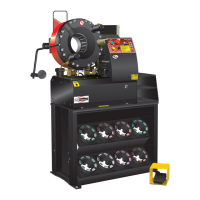
FIG. 2
WHEN USING 21 AND 22 DIES
Using Gates dial calipers (Product No.
7369-0322, Part No. 78215) measure halfway
between ridges (Fig. 1). To be sure crimp diameter
is being properly measured, mark a crimp flat.
Beginning with that flat, count 9 flats to get the
diameter. Be sure caliper blades DO NOT touch
ridges. (See Photo 3.)
Measure halfway between the ends of crimped
portion of the ferrule (Fig. 2).
Should actual crimp diameter not be within
recommended crimp tolerance, check calibration
of the machine and recalibrate. If the machine is
properly calibrated, you may need to make a slight
adjustment to the digital readout.
WHEN NOT USING 21
AND 22 DIES
Using Gates dial calipers (Product No. 7369-0322,
Part No. 78215) which are notched to clear ridges,
measure halfway between ridges (Sketch 1). Be sure
caliper fingers DO NOT touch ridges or part number
stamps. (See Photo 3.)
Measure halfway down the crimped portion of the
ferrule (Sketch 2).
To obtain a smaller crimp diameter, change digital
read out setting to smaller number. To get a larger
crimp diameter, change digital readout setting to a
larger number. Changing digital readout number by
.05 will change crimp diameter .001”. Record new
setting on your crimp data chart for future reference.
MEASURING CRIMP DIAMETER
PC 707 CRIMPER SAFETY AND OPERATING MANUAL
1.
2.
1.
3.
2.
4.
PHOTO 3