GBA
Global Bill Acceptors
GBA ST2
Operations Manual
Page 17 of 25
Astrosys International Ltd
January 2009
GBA ST2 Op Manual V1.01
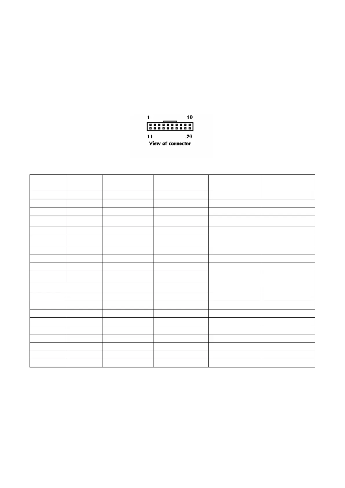
8.0 ELECTRICAL CONNECTIONS
Please note: care should be taken to avoid reversing the Ground and 12VDC connections, as this will
cause damage to the unit.
Pin Parallel
Mars Serial
Pulse Serial (R1)
1
Grey /ABN Output /ABN Output /ABN Output
n.c.
2
Orange n.c. /Serial Select (Low) Pulse (High) or n.c.
n.c.
3
White /Vend 6 Output /Busy /Busy
n.c.
4
Yellow /Escrow control Clears /ABN and
Stacker Full Signal
Clears /ABN and
Stacker Full Signal
n.c.
5
Green / Vend 5 Output TXD n.c.
TXD
6
Brown n.c. Serial Send Signal
(/RTS)
n.c.
n.c.
7
Black / Vend 3 Output Gnd n.c.
n.c.
8
Red / Vend 4 Output n.c. n.c.
n.c.
9
Whi/Blk/Grn n.c. n.c. n.c.
RXD
10
Blue Inhibit Control Input
(/Enable)
Inhibit Control Input
(/Enable)
Inhibit Control Input
(/Enable)
n.c.
11
Violet / Vend 1 Output Confirm Signal To Start
Serial (/CTS)
n.c.
n.c.
12
Whi/Vio n.c. n.c. /Pulse O/P
n.c.
13
Whi/Gry / Vend 2 Output n.c. n.c.
n.c.
14
Whi/Blk Motor Ground Motor Ground Motor Ground Motor Ground
15
Whi/Blk Ground Ground Ground Ground
16
Whi/Red 12 VDC + 12 VDC + 12 VDC + 12 VDC +
17
Whi/Red 12 VDC + 12 VDC + 12 VDC + 12 VDC +
18
Whi/Yel PDT Terminal PDT Terminal PDT Terminal PDT Terminal
19
Whi/Grn PDT Terminal PDT Terminal PDT Terminal PDT Terminal
20
Whi/Blu PDT Terminal PDT Terminal PDT Terminal PDT Terminal
Note: where a description is preceded by a “/” then that signal is active low.
n.c. = not connected
*for cctalk
®
interface, please note that TXD & RXD must both be connected to the DATA line of the
host machine.
See also Interface Description Manual for further details.