6 ESL 1500 Series Fire Alarm Control Panel
System Reset
System reset can only be accomplished when all actuated alarm devices have been restored to their normal, standby condition.
Note: Operating the system reset switch will return all alarm initiating circuits and system-powered inititating
devices to their normal standby condition. Mechanical initiating devices such as most fixed termperature heat
detectors and manual stations must be replaced or manually reset or the system will alarm again when the reset
switch is released.
Trouble Condition
Activation of the fault signal under normal operation indicates a condition that requires immediate correction. A fault signal
involves illumination of the system trouble LED (yellow) and individual diagnostic LED’s (yellow) generally associated with the
specific circuit affected. The integral sounder will sound a slow intermittent signal and a set of dry, Form C contacts will transfer.
Moving the SOUNDER SILENCE switch to the silence position will silence the audible trouble signal, but will not restore the
Form C contacts. Restoration to normal can only be achieved when all faults have been corrected and all switches have been
returned to normal position. Trouble reset occurs automatically when this is accomplished. If the SOUNDER SILENCE switch is
off-normal at the time all faults are clear, the “ringback” feature will alert the operator.
Supervisory Functions
Zone 2 of the control panel can be programmed for supervisory service. A common supervisory application would include
sprinkler water valve tamper switch monitoring. During a supervisory alarm, the integral sounder activates a rapidly pulsing tone
and the zone 2 red local alarm LED lights. In addition, the supervisory LED on the BMB will activate. During supervisory
trouble, the integral sounder activates a rapidly pulsing tone, zone 2 yellow local trouble LED lights and the system trouble relay
contacts transfer.
Remote Test (Drill)
A remote test (drill) function is provided for testing the 1500 System. Closing a listed normally-open switch connected to
terminals “SYS GND” and FIRE DRILL” (see Figure 5) will result in actuating both the alarm indicating circuits and the integral
sounder. The common alarm relay will not operate, nor will an optional remote notification circuit. Any alarm signaling devices
connected to the indicating circuits will be activated. During the test/drill, the indicating supervisory circuit will be tested as well,
resulting in the illumination of the indicating circuit fault LED’s and the system trouble LED. The integral sounder will sound a
slow intermittent signal.
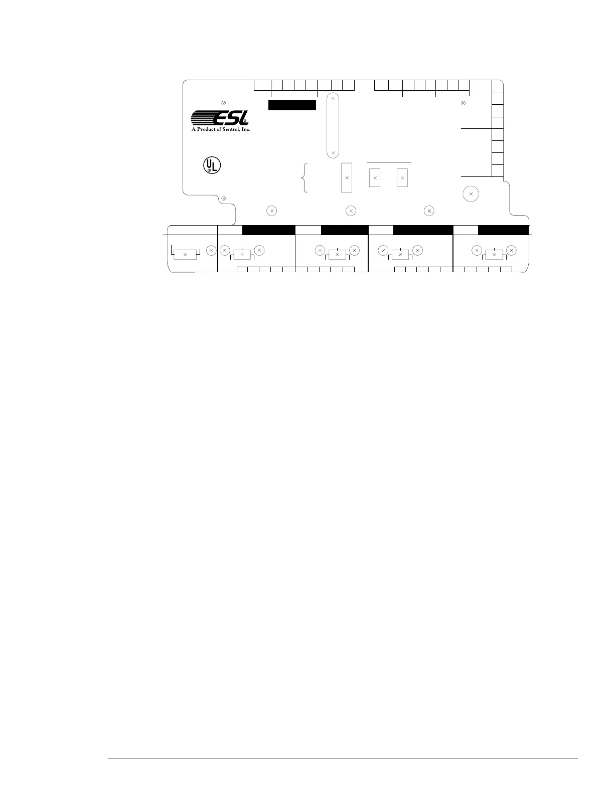
Figure 4. Template Diagram
24 VAC
AC IN
24 VDC
BATTERY IN
ZONE 1 TROUBLE
SUPERVISORY
LOW/NO AC POWER
LOW/NO BATTERY
GROUND FAULT
INDICATING 1 TROUBLE
INDICATING 2 TROUBLE
SYSTEM
POWER LIMITED
NORMAL NORMAL
RESET SOUNDER
SILENCE
SYSTEM
TROUBLE
ZONE
ALARM
WALKTEST
NORMAL
DISCONNECT
ZONE
1
AC
POWER
COMMUNICATOR ZONE
2 ZONE 3 ZONE 4 ZONE 5
DISCONNECT WALKTEST
DISCONNECT WALKTEST DISCONNECT WALKTEST
ALARM TRBL
NORMAL
DISCONNECT
NORMAL
TRBL
ALARM TRBL
NORMAL
ALARM TRBL
NORMAL
ALARM TRBL
NORMAL
DISCONNECT WALKTEST
NOT USED–8
NOT USED–7
NOT USED–6
ZONE 2 SUP.–5
ZONE 1 RA–4
SILENT WALKTEST–3
ZONE 1 WATERFLOW–2
ALARM VERIFICATION–1
INDICATING
1
INDICATING
2
Z1RA– COM NO NC COM NC NO
TROUBLE RELAY ALARM RELAY
CASE
GROUND
Z1B+ Z1A+ Z1A– Z1B–
AUX
24VFWR
SYS
GND
FIRE
DRILL
ZONE
1
1
SENTROL, INC.
12345 SW Leveton Drive
Tualatin, Oregon 97062
SYSTEM
+15VDC
B–
B+
A+
A–
B–
B+
A+
A–
Z2B+
Z2A+ Z2A- Z2B- Z2RA- Z3B+ Z3A+ Z3A- Z3B- Z3RA-
Z4B+
Z4A+ Z4A- Z4B- Z4RA- Z5B+ Z5A+ Z5A- Z5B- Z5RA-