14 ESL 1500 Series Fire Alarm Control Panel
Figure 13. ZEM Default Settings
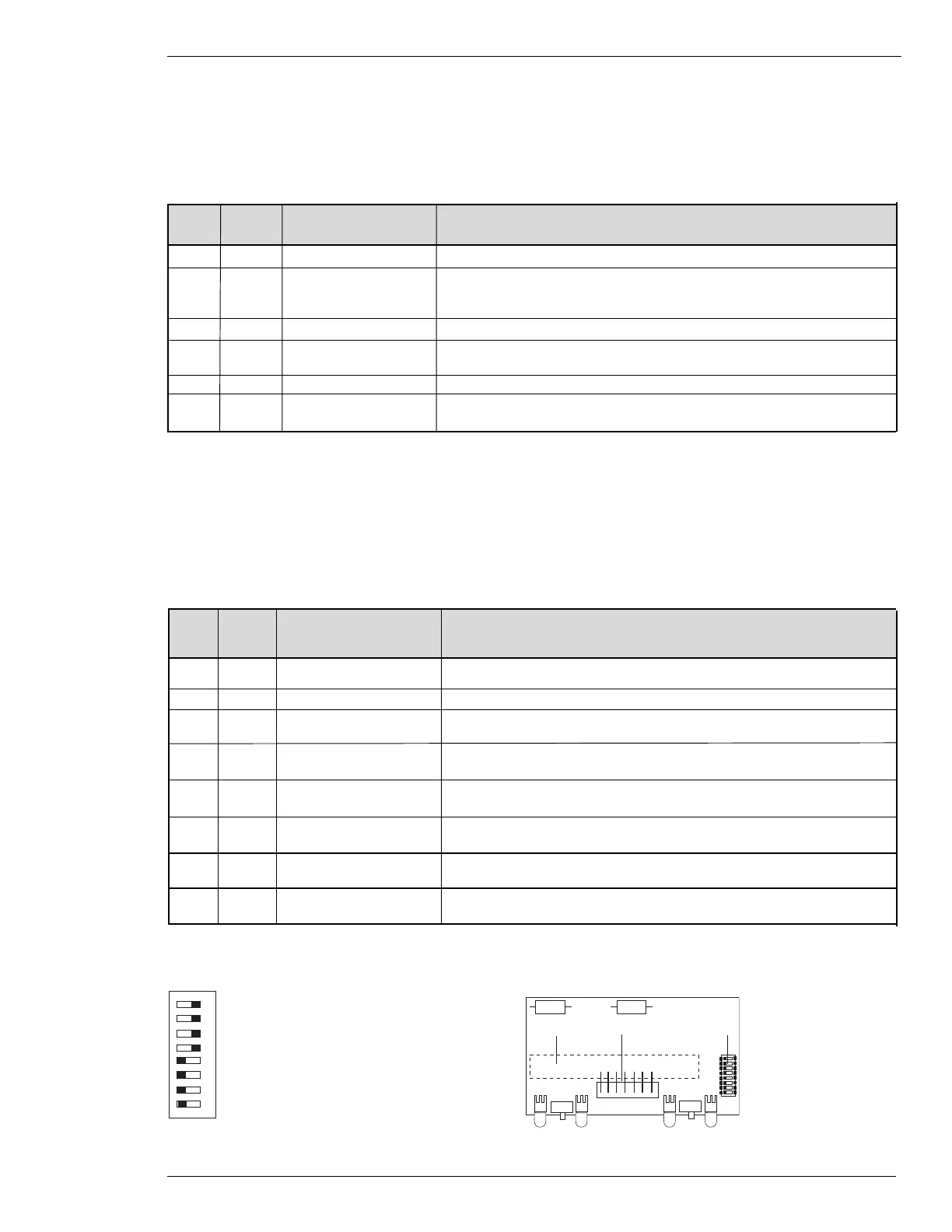
Figure 14. ZEM Programming Switches Location
1. Terminal Block
2. 7-Pin Header
3. DIP Switches
1 2 3
ON
1
2
3
4
5
6
7
8
8-Zones 3 and 5 Waterflow
7-Zones 2 and 4 Waterflow
6-Zone 2 Supervisory
5-Zone 2 Supervisory
4-Zone 2 Supervisory
3-Zone 2 Supervisory
2-Zones 3 and 5 Remote Annunciator
1-Zones 2 and 4 Remote Annunciator
ZEM Programming
All programming selections are controlled by switches located in the front right center of the ZEM. Table 6 shows default
(factory) programming along with a description of each feature.
Table 6. ZEM Programming Features
Switch Factory Feature Description
# Position
8 off zones 3 & 5 waterflow* Alarm disconnect switch enabled. Signals can be silenced.
7 off zones 2 & 4 waterflow* Alarm disconnect switch enabled. Signals can be silenced.
6 off zone 2 supervisory Fire alarm signal enabled. Yellow supervisory LED on 1500-BMB is diabled.
See Supervisory Functions.
5 off zone 2 supervisory Fire alarm signal enabled. Yellow supervisory LED on 1500-BMB is disabled.
See Supervisory Functions.
4 on zone 2 supervisory Fire alarm signal enabled. Yellow supervisory LED on 1500-BMB is disabled.
See Supervisory Functions.
3 on zone 2 supervisory Fire alarm signal enabled. Yellow supervisory LED on 1500-BMB is disabled.
See Supervisory Functions.
2 on zone 3 & 5 Remote Connection to remote indicator not supervised.
Annunciator
1 on zone 2 & 4 Remote Connection to remote indicator not supervised.
Annunciator
* Do not program zones for waterflow in conjunction with walktest because the communicator or optional LEM module may
transmit an alarm condition. In addition, the sytem alarm relay will be activiated.
Programming
BMB Programming
All programming selections are controlled by switches located in the lower right corner of the BMB. Table 5 shows default
(factory) prgramming along with a description of each feature.
Table 5. BMB Programming Features
Switch Factory Feature Description
# Position
8,7,6 off not used not used
5 off zone 2 supervisory Disables fire alarm signal and provides distinctive audible and visual supervi-
sory signals. Must also program ZEM zone 2 switches 3, 4, 5, & 6. See ZEM
Programming.
4 off zone 1 remote Provides supervised annunciator connection to remote alarm indicator.
3 off silent walktest Silences indicating circuits 1 & 2 during walktest mode. See Zone
Disconnect/Walktest.
2 off zone 1 waterflow* Disables alarm disconnect switch. Signals cannot be silenced.
1 off alarm verification Two consecutive alarm input signals required for alarm output. See Alarm
Verification.
* Do not program zone for waterflow in conjunction with walktest because the communicator or optional LEM module may
transmit an alarm condition. In addition, the sytem alarm relay will be activiated.