7
ESL 1500 Series Fire Alarm Control Panel
Field Wiring
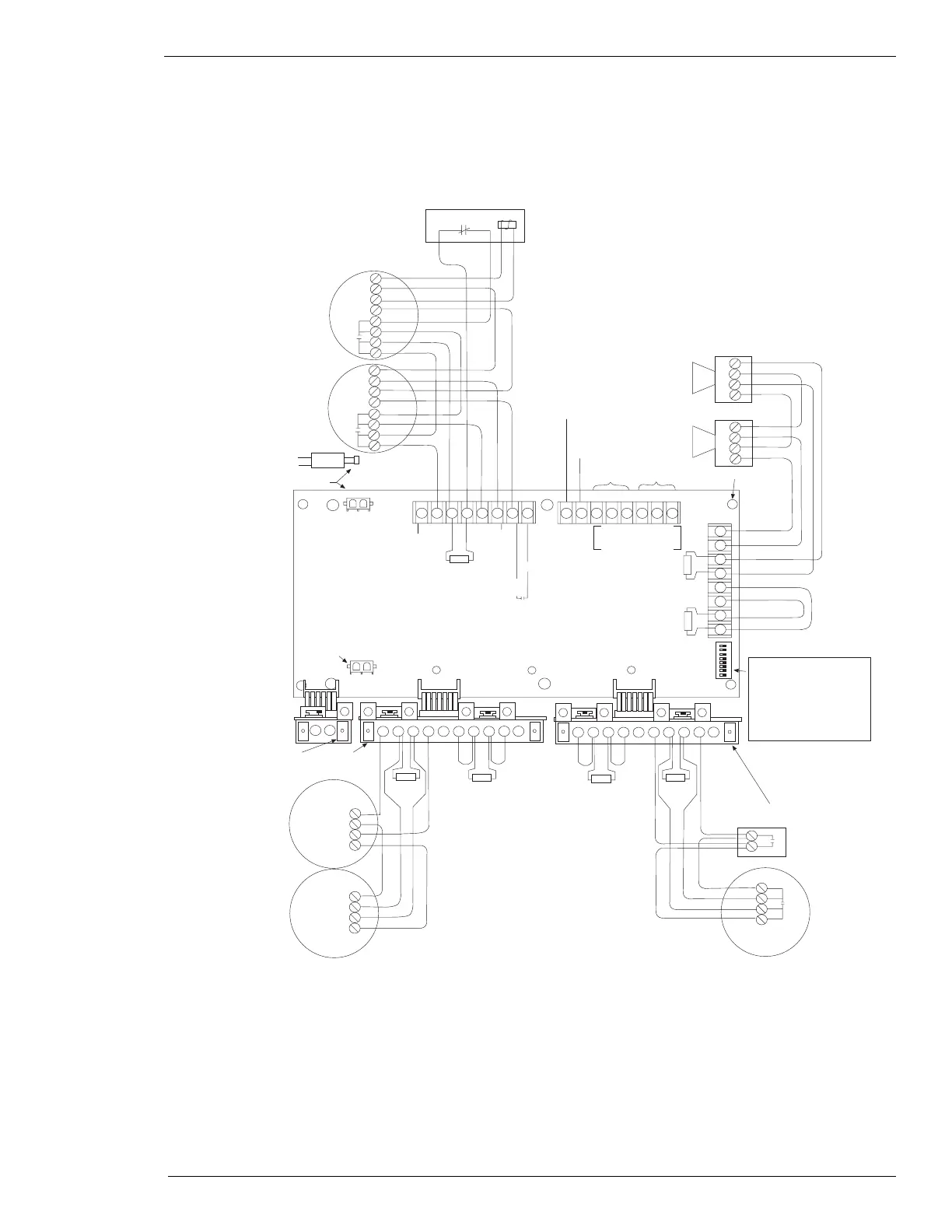
Class A System Wiring Diagram
Connect to
120 V AC
60Hz
Connector from
transformer
Blk
Wht
Case
ground
Auxiliary
power(+)
Optional drill
test switch
Fire drill
1678
Local Zone 1 alarm
(Supervised)
System 15VDC
System trouble
contacts
Auxiliary alarm
contacts
BMB standoff
910111213141516
17
18
19
20
21
22
23
24
Zone 1
Zone 1
alarm
System
trouble
AC
power
Connector from
24 V DC battery in
BMB
8-Not used
7-Not used
6-Not used
5-Zone 2 supervisory
4-Zone 1 remote annunciator
3-Silent walktest
2-Zone 1 waterflow
1-Alarm verification
12
RA
B+
A+ A- B- RA B+ A+ A- B-
LEM
ZEM
Zone 4 & 5
ZEM
Zone 2 & 3
System
GND
ON
1
2
3
4
5
6
7
8
+
+
-
-
+
+
-
-
429C
429C
2.7K EOL
Resistor 1/2W
Pull station
Heat sensor
2.7K EOL
Resistor
1/2W
-
-
+
+
449C
449C
Zone 2
Zone 3
Zone 4 Zone 5
-
-
+
+
-
-
+
+
-
-
+
+
2.7K EOL
Resistor
1/2W
204-12/24V
Power
supervision relay
2.7K EOL
Resistor 1/2W
RA
B+
A+ A- B- RA B+ A+ A- B-
B+ A+ A- B-
B-
B+
A+
A-
B-
B+
A+
A-
Zone 1 is shown with 4-wire
detectors, wired in Class A (Style D)
C N/O N/C C N/C N/O
Power ON
(standby condition)
2.7K EOL
Resistor 1/2W
2.7K EOL
Resistor 1/2W
Zone 2 is shown with 2-wire
detectors, wired in Class A (Style D)
Zone 5 is shown with 2-wire heat
detectors and pull stations, wired in
Class A (Style D)
2.7K EOL
Resistor 1/2W
Bell circuit 1 is shown with Class
A
(Style Z) wiring
Figure 5. Class A System Wiring Diagram