12 ESL 1500 Series Fire Alarm Control Panel
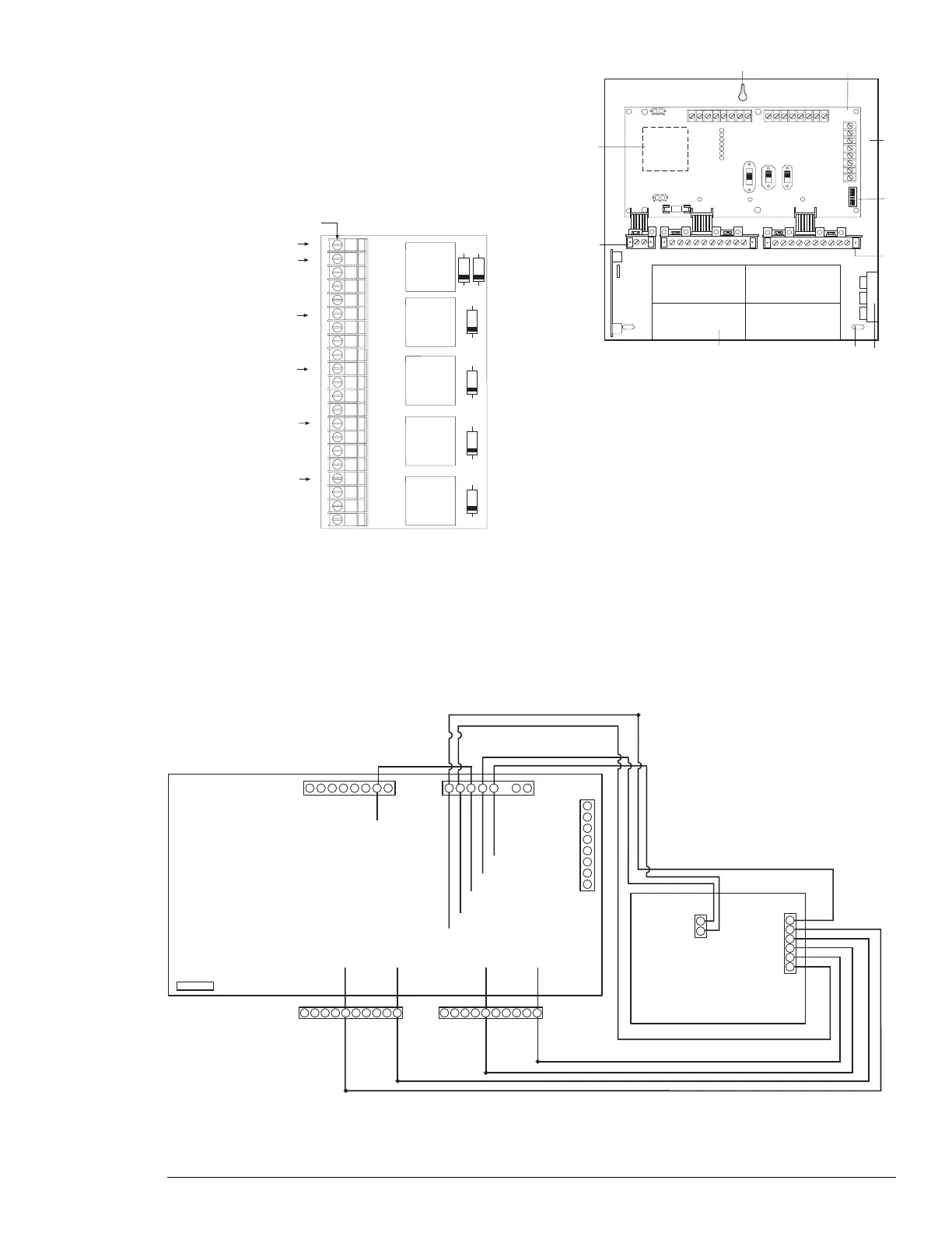
1
2
3
4
5
6
7
8
9
10
11
12
13
14
15
16
17
18
19
20
21
COM
COIL
N/O
C
N/C
COIL
N/P
C
N/C
COIL
N/O
C
N/C
COIL
N/O
C
N/C
COIL
N/O
C
N/C
K1
K2
K3
K4
K5
D6 D1
D2
D3
D4
D5
System+15 VDC of BMB
To Z1RA-of BMB
(Zone)
To Z2RA-of ZEM
(Zone 2)
To Z3RA-of ZEM
(Zone 3)
To Z4RA-of ZEM
(Zone 4)
To Z5RA-of ZEM
(Zone 5)
TB1
Figure 8. Zone Relay Module (ZRM) Wiring Diagram Figure 9. Zone Relay Module (ZRM) Placement
ON
1
2
3
4
5
6
7
8
Zone #1 trouble
Supervisory
Low/no AC
Low/no battery
Ground fault
Indicating #1 trouble
Indicating #2 trouble
1
2
3
4
5
67
8
9
10
1. Mounting hole
2. Basic Master Board (BMB)
3. Housing backbox
4. Programming switches
5. Zone Expander Modules (ZEM)
6. Mounting location for Zone Relay Module 1500-ZRM-5
7. Mounting hole
8. Battery area
9. Local Energy Master Box Trip Module 1500-LEM
10. 1500-TR Transformer
Figure 10. Terminal Connections
Zone 1 input
Zone 2 input
Zone 3 input
Zone 4 input
Zone 5 input
+ 15 VDC
TB1
TB2
Tip
Case Ground
SYS-
Communicator
ESL 1500 BMB
Z2RA- Z3RA- Z4RA Z5RA-
Trouble input
Trouble input
TB3
ALM NO
ALM NC
TRB NC
TRB NO
TRB COM
RA+15
Z1RA-
1500 RA5A