3
ESL 1500 Series Fire Alarm Control Panel
Installing the Panel
To install the unit, follow these 12 steps, and refer to the proper sections for more information.
1. Create System Diagram: Prepare a carefully laid out drawing of the complete wiring system hookup. Maintain this
drawing as a permanent record of the system application and include any future modifications.
Note: “As-built” drawings and this manual should be available at all times to verify agreement between the
connected equipment and the drawings.
2. Inspect Equipment: Carefully unpack the system components and inspect for shipping damage. Report any shipping
damage to place of purchase.
3. Mount Cabinet: Mount the cabinet in a clean, dry, vibration-free area, where the temperature range does not exceed 0°
to 49° C (32° to 120° F). Mount only in interior locations. Allow adequate space for 180 degree door swing and free
access to sides for conduit entry. Locate the top of the cabinet approximately 6 feet (1.8m) above the floor, with the hinge
mounting on the left. Mounting holes in the back of the cabinet are designed so the cabinet can be mounted without removing
any control equipment. Mount the cabinet to the wall by first installing the top center mounting screw, leaving enough space
so the cabinet can be hooked over the screw head. Use screws or bolts no smaller than #10 or 3/16 inches in diameter. For
easier access, remove the door by gently lifting it from the hinges.
4. Connect Conduit: Complete all connections to the cabinet with conduit fittings or bushings. Use the knockouts provided in
the sides of the cabinet.
5. Pull Wire: Pull all system wiring through installed conduit following the guidelines of Article 760 of the National Electrical
Code (NFPA 70) and/or local codes for fire alarm systems. Observe power limiting codes when running wire.
See Installation Recommendations/Precautions for more information.
6. Program Components: Before wiring, examine installation of all modules, chassis and sub-assemblies to ensure proper
mechanical and electrical connections and programming switches have been selected. See Programming for options.
7. Connect AC: Connect line voltage to transformer leads located under the BMB. Transformer wires are long enough
so you do not need to remove the circuit board.
8. Connect Batteries: Determine the total system power requirements by using the Standby Battery Power Worksheet
in Appendix B.
9. System Check: Make certain the 1500 panel is operating properly before connecting field wiring by performing a
system check. ESL makes this easy by factory installing end-of-line resistors to the proper Class B zone terminals. To test
the panel, make sure all switches are in their normal position and power the system by connecting AC and then the
batteries. (Note: if new batteries with low terminal voltage are used, the Low/No Battery LED may activate. The Low
Battery indicator will deactivate after the batteries are fully
charged - no longer than 48 hours.) No fault indications
should be present. If faults are present, see Table 6. Trouble-
shooting Guide. System check is now complete.
10. Check Field Wiring: Check the integrity of all field wiring
following directions defined in the Field Wiring Checkout
Procedures.This check must be performed before connecting
wiring to the system. Becertain all external wiring is correct
(no opens, shorts, or grounds) and is terminated with the
correct end-of-line devices.
11. Connect Field Wiring: Connect each circuit in turn,
following wiring diagrams provided. Do not make all
connections at once. This procedure will let you bring your
system on-line in stages and quickly identify which portion of
your system is not working.
Note: NFPA 72, Chapter 7 - Inspection, Testing, and
Maintenance should serve as the guideline for all system tests.
12. Test System: Apply power and perform operational tests as
outlined under Testing and System Checkout.
CAUTION
Read and understand all instructions before beginning
installation. System reliability depends upon proper
installation, testing, and maintenance. Review all national
and local codes before attempting installation. Refer to
National Fire Alarm Code (NFPA 72) for proper location,
mounting, etc. of smoke detectors, heat detectors, and
other alarm initiating devices. Call Technical Support at
800.648.7424 if you have installation questions.
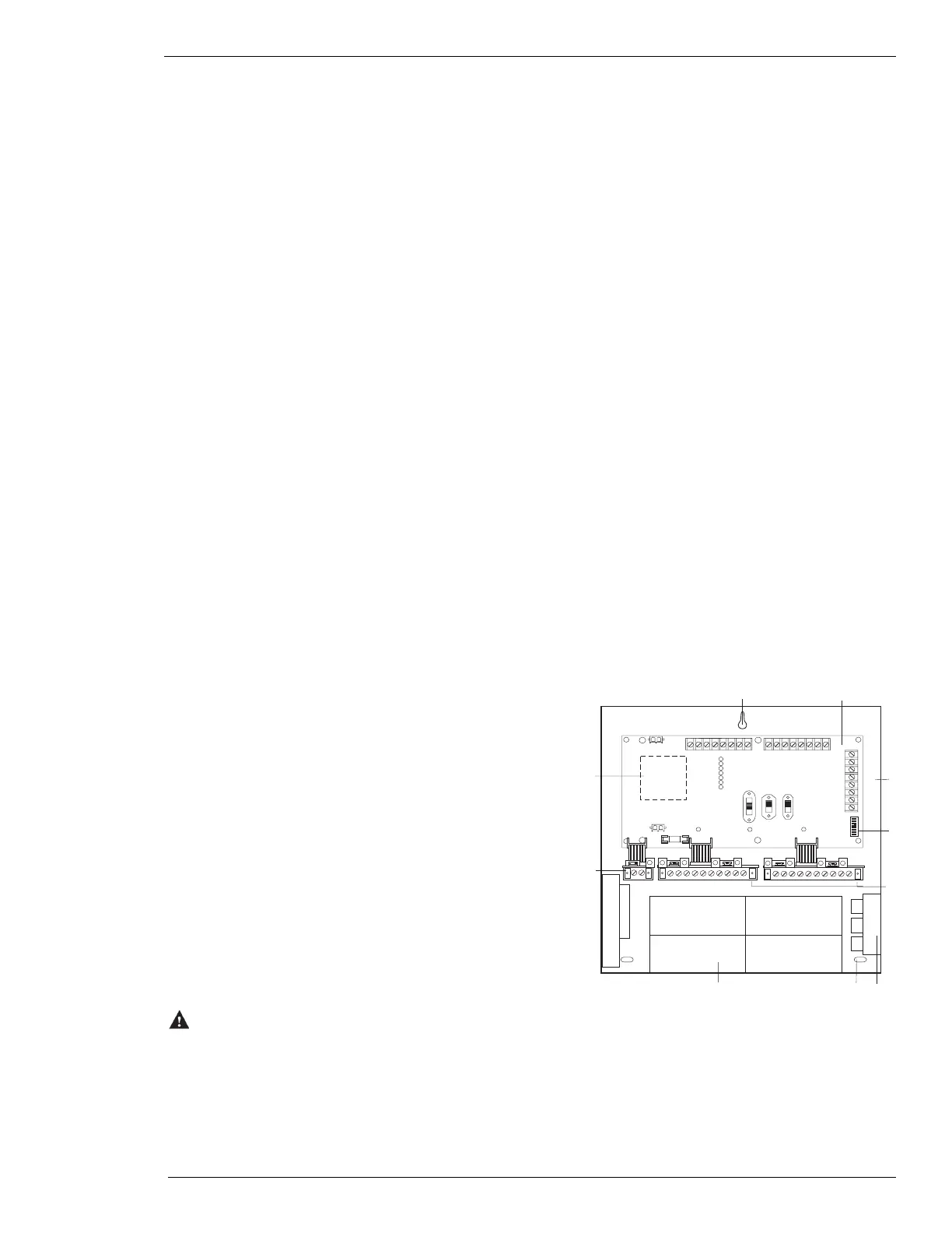
Figure 1. Internal Panel Confirguration
ON
12345678
Zone #1 trouble
Supervisory
Low/no AC
Low/no battery
Ground fault
Indicating #1 trouble
Indicating #2 trouble
1
2
3
4
5
6
7
8
10
9
1. Mounting hole
2. Basic Master Board (BMB)
3. Housing backbox
4. Programming switches
5. Zone Expander Modules (ZEM)
6. Mounting location for Zone Relay Module 1500-ZRM-5
7. Mounting hole (TYP)
8. Battery area
9. Local Energy Master Box Trip Module 1500-LEM
10. 1500-TR Transformer