GE Power Management
489 Generator Management Relay 5-1
5 ACTUAL VALUES 5.1 OVERVIEW
5
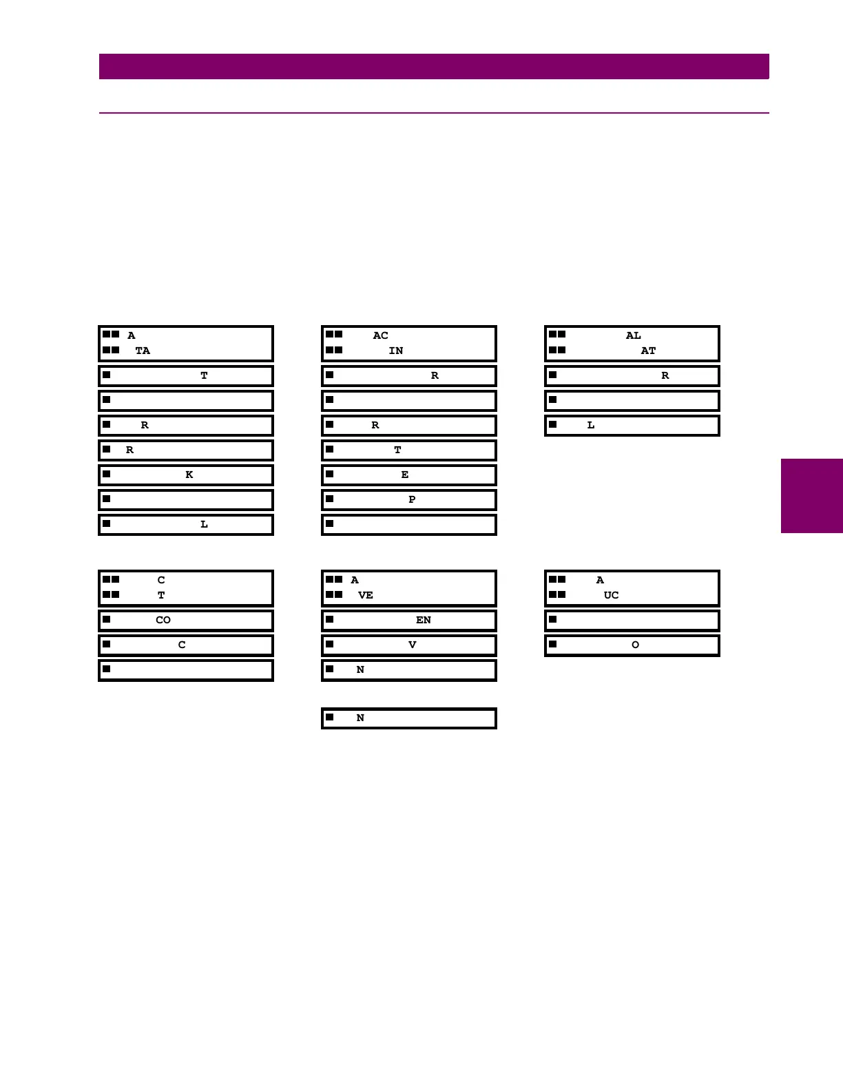
5 ACTUAL VALUES 5.1 OVERVIEW 5.1.1 ACTUAL VALUES MESSAGES
Measured values, maintenance and fault analysis information are accessed in the Actual Value mode. Actual values may
be accessed via one of the following methods:
1. Front panel, using the keys and display.
2. Front program port, and a portable computer running the 489PC software supplied with the relay.
3. Rear terminal RS485 port, and a PLC/SCADA system running user-written software.
Any of these methods can be used to view the same information. However, a computer makes viewing much more conve-
nient since many variables may be viewed simultaneously.
Actual value messages are organized into logical groups, or pages, for easy reference, as shown below. All actual value
messages are illustrated and described in blocks throughout this chapter. All values shown in these message illustrations
assume that no inputs (besides control power) are connected to the 489.
In addition to the actual value messages, there are also diagnostic and flash messages that appear only when certain con-
ditions occur. They are described later in this chapter.
A1 ACTUAL VALUES
STATUS
A2 ACTUAL VALUES
METERING DATA
A3 ACTUAL VALUES
LEARNED DATA
GENERATOR STATUS
CURRENT METERING
PARAMETER AVERAGES
LAST TRIP DATA
TEMPERATURE
RTD MAXIMUMS
ALARM STATUS
POWER METERING
ANALOG IN MIN/MAX
TRIP PICKUPS
TEMPERATURE
ALARM PICKUPS
DEMAND METERING
DIGITAL INPUTS
ANALOG INPUTS
REAL TIME CLOCK
SPEED
A4 ACTUAL VALUES
MAINTENANCE
A5 ACTUAL VALUES
EVENT RECORD
A6 ACTUAL VALUES
PRODUCT INFO.
TRIP COUNTERS
[ENTER] EVENT 01
489 MODEL INFO.
GENERAL COUNTERS
[ENTER] EVENT 02
CALIBRATION INFO.
TIMERS
[ENTER] EVENT 03
↓
[ENTER] EVENT 40