GE Power Management
489 Generator Management Relay 4-41
4 SETPOINT PROGRAMMING 4.8 S7 POWER ELEMENTS
4
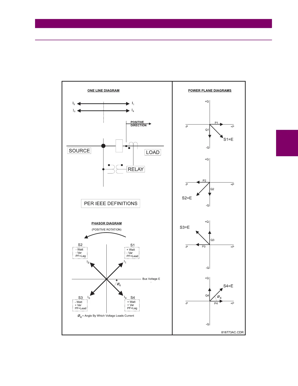
4.8 S7 POWER ELEMENTS 4.8.1 POWER MEASUREMENT CONVENTIONS
Generation of power will be displayed on the 489 as positive watts. By convention, an induction generator normally requires
reactive power from the system for excitation. This is displayed on the 489 as negative vars. A synchronous generator on
the other hand has its own source of excitation and can be operated with either lagging or leading power factor. This is dis-
played on the 489 as positive vars and negative vars, respectively. All power quantities are measured from the phase-
phase voltage and the currents measured at the output CTs.
Figure 4–9: POWER MEASUREMENT CONVENTIONS
I
1
I
2
I
3
I
4
^
^
^
^