7-12 489 Generator Management Relay
GE Power Management
7.3 ADDITIONAL FUNCTIONAL TESTING 7 TESTING
7
7.3.4 VOLTAGE PHASE REVERSAL TEST
The can detect voltage phase rotation and protect against phase reversal. To test the phase reversal element, perform the
following steps:
1. Alter the following setpoints:
S2 SYSTEM SETUP\VOLTAGE SENSING\VT CONNECTION TYPE:
Wye
S2 SYSTEM SETUP\GEN. PARAMETERS\GENERATOR PHASE SEQUENCE:
ABC
S3 DIGITAL INPUTS\BREAKER STATUS\BREAKER STATUS:
Breaker Auxiliary a
S6 VOLTAGE ELEMENTS\PHASE REVERSAL\PHASE REVERSAL TRIP:
Unlatched
S6 VOLTAGE ELEMENTS\PHASE REVERSAL\ASSIGN TRIP RELAYS:
Trip
2. Apply voltages as per the table below. Verify the operation on voltage phase reversal
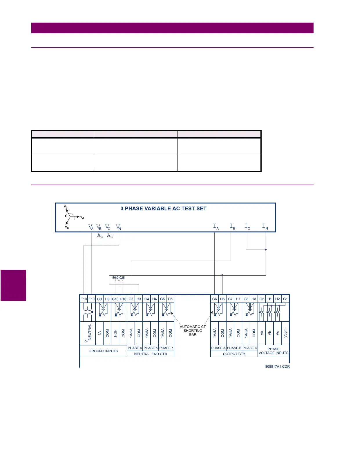
7.3.5 INJECTION TEST SETUP #2
Setup the 489 device as follows for the following tests.
Figure 7–2: SECONDARY INJECTION SETUP #2
APPLIED VOLTAGE EXPECTED RESULT OBSERVED RESULT
Va = 120 V
∠
0
°
Vb = 120 V
∠
120
°
lag
Vc = 120 V
∠
240
°
lag
NO TRIP
Va = 120 V
∠
0
°
Vb = 120 V
∠
240
°
lag
Vc = 120 V
∠
120
°
lag
PHASE REVERSAL TRIP