GE Power Management
489 Generator Management Relay 6-41
6 COMMUNICATIONS 6.3 MEMORY MAP
6
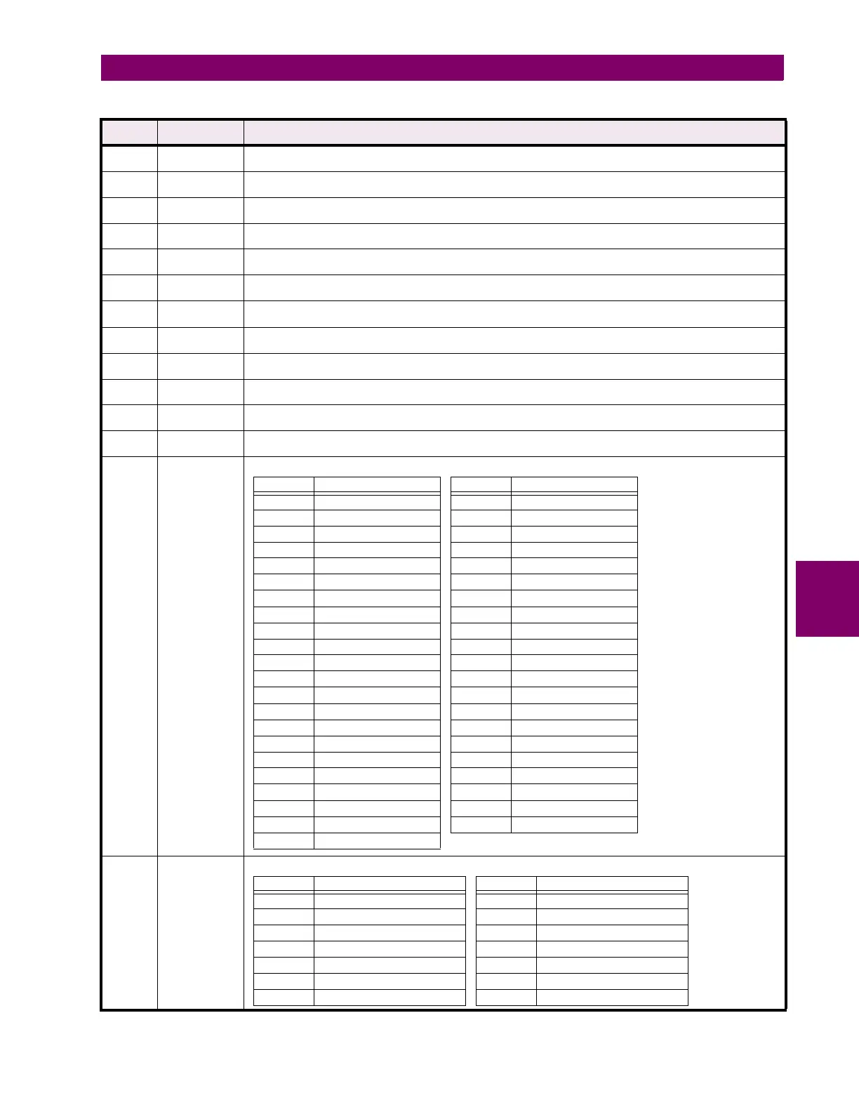
F106 Unsigned
16 bit integer
VT connection type
0 = None, 1 = Open Delta, 2 = Wye
F107 Unsigned
16 bit integer
Nominal frequency selection
0 = -----, 1 = 60 Hz, 2 = 50 Hz, 3 = 25 Hz
F109 Unsigned
16 bit integer
Breaker status switch type
0 = Auxiliary a, 1 = Auxiliary b
F115 Unsigned
16 bit integer
Alarm / trip type selection
0 = Off, 1 = Latched, 2 = Unlatched
F117 Unsigned
16 bit integer
Reset mode
0 = All Resets, 1 = Remote Reset Only
F118 Unsigned
16 bit integer
Setpoint Group
0 = Group 1, 1 = Group 2
F120 Unsigned
16 bit integer
RTD type
0 = 100 Ohm Platinum, 1 = 120 Ohm Nickel, 2 = 100 Ohm Nickel, 3 = 10 Ohm Copper
F121 Unsigned
16 bit integer
RTD application
0 = None, 1 = Stator, 2 = Bearing, 3 = Ambient, 4 = Other
F122 Unsigned
16 bit integer
RTD voting selection
1 = RTD #1, 2 = RTD #2, 3= RTD #3,..., 12 = RTD #12
F123 Unsigned
16 bit integer
Alarm / trip status
0 = Not Enabled, 1 = Inactive, 2 = Timing Out, 3 = Active Trip, 4 = Latched Trip
F124 Unsigned
16 bit integer
Phase rotation selection
0 = ----, 1 = ABC, 2 = ACB
F126 Unsigned
16 bit integer
Disabled / Enabled selection
0 = Disabled, 1 = Enabled
F127 Unsigned
16 bit integer
Analog output parameter selection
F128 Unsigned
16 bit integer
Overcurrent curve style selection
Table 6–2: DATA FORMATS (Sheet 2 of 5)
FORMAT
CODE
TYPE DEFINITION
7
8
9