GE Power Management
489 Generator Management Relay B-5
APPENDIX B B.1 STATOR GROUND FAULT PROTECTION
B
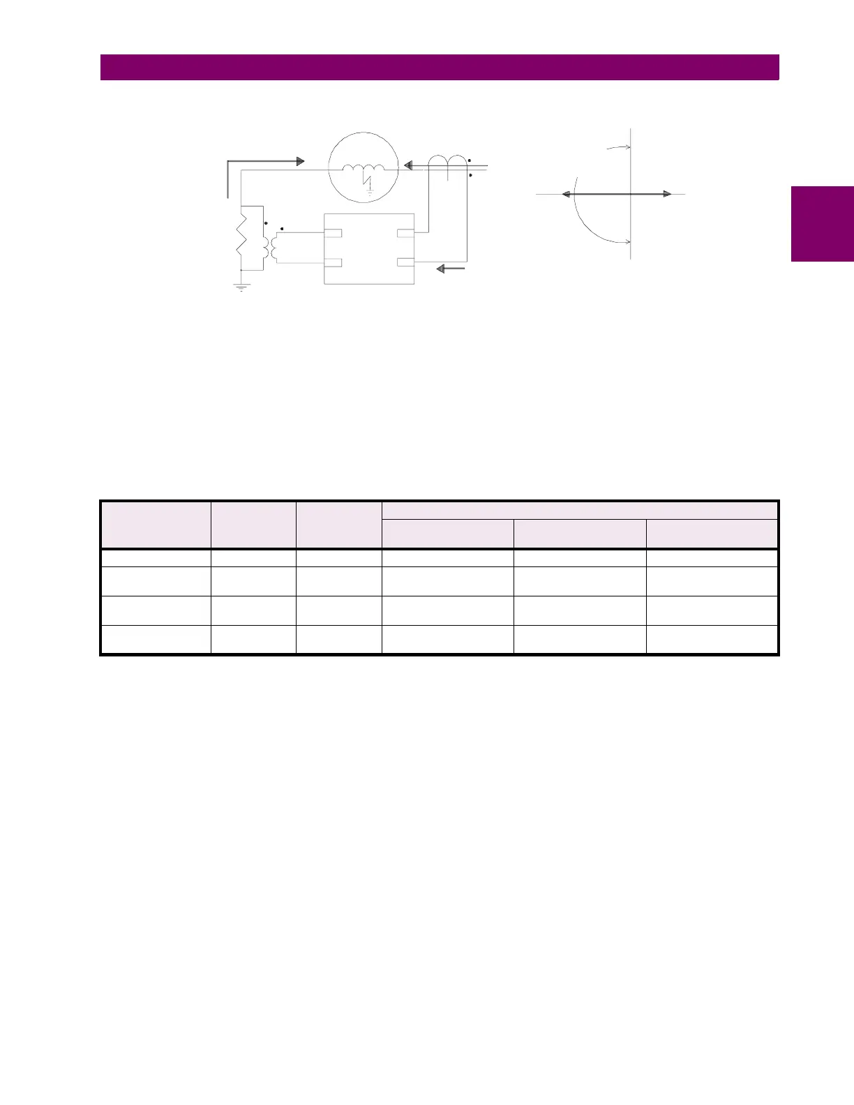
Figure B–5: GROUND DIRECTIONAL ELEMENT POLARITIES AND PLANE OF OPERATION
Applications with generators operated in parallel and grounded through a common impedance require special consider-
ations. If only one generator is grounded and the other ones left floating, the directional element for the floating generators
does not receive a correct
V
neutral
signal and therefore cannot operate correctly. In those applications, the element makes
use of auxiliary contacts off the grounding switch and the unit breaker to turn the element into a simple overcurrent element,
with the pickup level set for the directional element (note that the ground directional element and the ground overcurrent
elements are totally separate elements). In this mode, the element can retain a high sensitivity and fast operate time since
it will only respond to internal stator ground faults. The table below illustrates the status of different elements under various
operating conditions.
Table B–1: DETECTION ELEMENT STATUS
GENERATOR
CONDITION
UNIT
BREAKER
GROUNDING
SWITCH
ELEMENT
GROUND
DIRECTIONAL
NEUTRAL
OVERVOLTAGE
GROUND
OVERCURRENT
Shutdown Open Open Out-of-service Out-of-service In-service
Open Circuit and
grounded
Open Closed In-service (but will not
operate due to lack of LO)
In-service In-service
Loaded and
Grounded
Closed Closed In-service In-service In-service
Loaded and Not
Grounded
Closed Open In service as a simple
overcurrent element
Out-of-service In-service
GDECON2R2.CDR
GENERATOR
I
o
CORE
BALANCE
CT
Plane of operation
for resistive
grounding impedance
180°
270°
0°
90°
Grounding
Resistor
Isolating
Transformer
489
Relay
V
o
F10
E10
H10
G10
Io
Io
Io
±
±