7.3.1 Harmonics Emission Requirements
Equipment connected to the public supply network:
Options Definition
1 IEC/EN 61000-3-2 Class A for 3-phase balanced
equipment (for professional equipment only up to 1
kW total power).
2 IEC/EN 61000-3-12 Equipment 16A-75A and profes-
sional equipment as from 1 kW up to 16A phase
current.
Table 7.7 Connected Equipment
7.3.2 Harmonics Test Results (Emission)
Power sizes from 0.75 kW and up to 18.5 kW in 200 V and
up to 90 kW in 460 V complies with IEC/EN 61000-3-12,
Table 4. Power sizes 110 - 450 kW in 460 V also complies
with IEC/EN 61000-3-12 even though not required because
currents are above 75 A.
Provided that the short-circuit power of the supply S
sc
is
greater than or equal to:
S
SC
=
3 ×
R
SCE
×
U
mains
×
I
equ
=
3 × 120 × 400 ×
I
equ
at the interface point between the user’s supply and the
public system (R
sce
).
It is the responsibility of the installer or user of the
equipment to ensure, by consultation with the distribution
network operator if necessary, that the equipment is
connected only to a supply with a short-circuit power S
sc
greater than or equal to specified above.
Other power sizes can be connected to the public supply
network by consultation with the distribution network
operator.
Compliance with various system level guidelines:
The harmonic current data in the table are given in
accordance with IEC/EN61000-3-12 with reference to the
Power Drive Systems product standard. They may be used
as the basis for calculation of the harmonic currents'
influence on the power supply system and for the
documentation of compliance with relevant regional
guidelines: IEEE 519 -1992; G5/4.
7.4 Galvanic Isolation (PELV)
7.4.1 PELV - Protective Extra Low Voltage
PELV offers protection by way of extra low voltage.
Protection against electric shock is ensured when the
electrical supply is of the PELV type and the installation is
made as described in local/national regulations on PELV
supplies.
All control terminals and relay terminals 01-03/04-06
comply with PELV (Protective Extra Low Voltage) (Does not
apply to grounded Delta leg above 400 V).
Galvanic (ensured) isolation is obtained by fulfilling
requirements for higher isolation and by providing the
relevant creapage/clearance distances. These requirements
are described in the EN 61800-5-1 standard.
The components that make up the electrical isolation, as
described below, also comply with the requirements for
higher isolation and the relevant test as described in EN
61800-5-1.
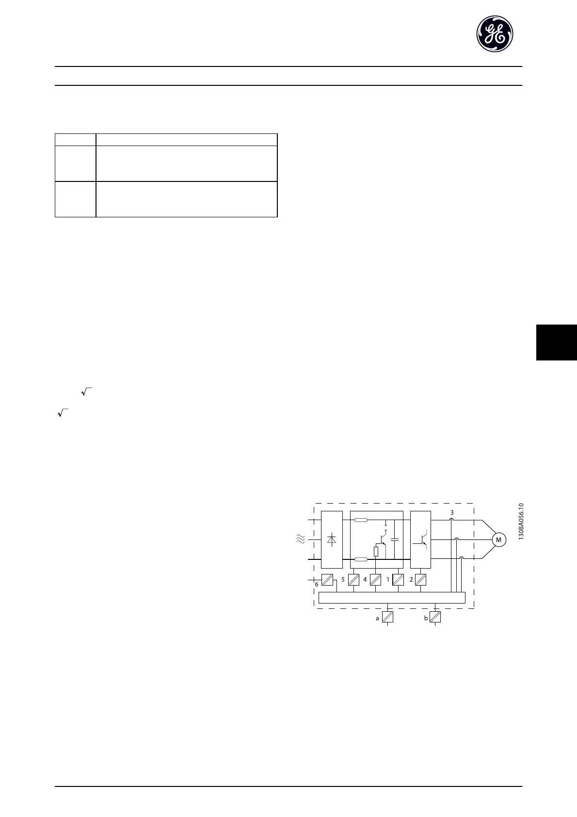
The PELV galvanic isolation can be shown in six locations
(see Illustration 7.3):
In order to maintain PELV all connections made to the
control terminals must be PELV, e.g. thermistor must be
reinforced/double insulated.
1. Power supply (SMPS) incl. signal isolation of U
DC
,
indicating the intermediate current voltage.
2. Gate drive that runs the IGBTs (trigger
transformers/opto-couplers).
3. Current transducers.
4. Opto-coupler, brake module.
5. Internal inrush, RFI, and temperature
measurement circuits.
6. Custom relays.
Illustration 7.3 Galvanic Isolation
The functional galvanic isolation (a and b on drawing) is
for the 24 V back-up option and for the RS 485 standard
bus interface.
Installation Consideration
AF-600 FP
TM
Design and Installation Guide
DET-768b 61
7

 Loading...


