EasyManua.ls Logo

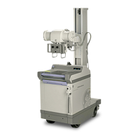
GE AMX-II

GE AMX-II
223 pages
To Next Page IconTo Next Page
To Previous Page IconTo Previous Page
Loading...
GENERAL
ELECTRIC
MEDICAL
SYSTEMS
AMX-II
X-RAY
UNIT
7-1576
SM
AO654E
SEC.
2A
INSTALL
HORIZONTAL
EXTENSION
ASSEMBLY
2-2
Install
Telescoping
Arm
The
unit
as
shipped
has
the
carriage
loaded
against
the
top
stops
of
the
vertical
column.
1.
Remove
the
telescoping
arm,
spacers
and
bracket
out
of
its
shipping
container.
2.
One
man
must
hold
the
arm
and
insert
the
two
studs
into
the
carriage.
See
Illustration
3-2.
)
YOKE
ROTATION
LOCK
|
INTERLOCK
BUTTON
——=5/16"
x
18
SPRING
TENS
ION
ADJUST
18698-P10
ILLUSTRATION
3-2
3.
A
second
man
must
place
the
bracket
over
the
top
of
the
arm
and
fasten
but
do
not
tighten,
with
three
5/16-
18
unc
x
1/2
hex
soc.
hd.
screws.
4.
Insert
enough
“UU”
shaped
spacers
(four
are
furnished
in
bag
no
2).
between
the
carriage
and
the
telescoping
arm
to
maintain
the
arm
in
a
horizontal
position.
Check
with
a
level
with
unit
on
a
level
floor.
5.
Tighten
the
three
screws
securing
the
bracket.
6.
Secure
the
two
carriage
studs
located
at
the
rear
of
the
carriage
with
two
5/16-18
unc
hex
hd
nuts
and
flat
washers.
7.
Loosen
the
carriage
lock
while
manually
holding
the
arm.
3-4

Related product manuals